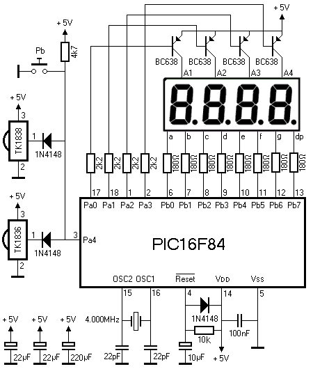
Schematic Diagram
All PIC IR Decoders share the same, easy to build, hardware. All parts for this hardware should be easily obtainable throughout the world. Building it shouldn't take very much longer than one evening.

At the heart of the diagram is the PIC16F84 processor.
It is accompanied by its standard components like a 4.000MHz crystal and reset circuitry.
BTW a PIC16C84 works equally well, just in case you have them lying around like I do.
I have used two types of IR receivers in this project, one tuned to a 36kHz carrier and the other to 38kHz.
This ensures adequate sensitivity for all supported protocols.
It's no problem if you can't get your hands on the exact same types that I have used.
There are plenty of similar receivers out there which can be used in exactly the same way.
The signals of both receivers are added together by 2 diodes before they are applied to PORTA bit 4 of the PIC.
Be sure to connect a 22µF capacitor close to the supply pins of each of the receivers.
The push button, which is also connected to the same input of the PIC, has no function at the moment.
I've included it just in case I decide to create a program that can read multiple IR protocols.
The push button can then be used to select the protocol.
The LED display concludes the description of the diagram.
It is simply a multiplexed 4 digit LED display.
I've used one with 4 digits in one package because it is far easier to wire than 4 separate one digit displays.
The individual segment current is limited by eight 180Ω resistors.
The common anodes of the 4 displays are driven by four PNP transistors.
If you can't find the type that I've used you can use practically any other PNP transistor which can drive peaks of about 200mA.
The circuit uses an external power supply of 5 V at about 100 mA average.

Building The PIC IR Decoder
 As usual I've built my device on a piece of pad board with Road-Runner wire.
No normal PCB has been designed for it.
Building on pad board has the advantage that it fast, easy and compact.
My board measures only 7x4cm.
Building the PIC IR Decoder requires no special skills.
As far as I can see there are no pitfalls in this project.
The only thing that I should mention (again and again) is to place the decoupling capacitors as close to the supply pins of the IC's as possible.
Both IR receivers are IC's too, you know!
I've used slightly thicker wire for all power lines.
If you save them for last you can fix the thinner wires with them as a bonus.
