Simple Go / No Go Testers
It doesn't take space technology to test whether an IR remote control actually works or not. This page will show you several very simple ways to verify the functionality of a remote control transmitter. It's up to you to pick the method that best suits your needs.
But what do we do if our remote appears not to work anymore? Well obviously we first check the health of its batteries, although I bet you had done that already. Probably the most likely cause of a malfunctioning remote control is that the LED has broken loose from the PCB. That is easy enough to fix....... if we can get the remote open that is.
Electronic Camera
By far the easiest way to test an IR remote control is to use an electronic camera.
I know it is not the cheapest way if you have to buy one for only testing a remote.
Therefore this option only applies if you already own one, but who doesn't in the current smart phone ages.
It doesn't really matter what kind of camera it is.
You can use a video cam-corder, a digital photo camera, a mobile phone with camera, or even a web-cam.
The only thing that really matters is that you must be able to see directly what the camera sees.
A digital camera without a monitor is not very useful in this case, unless you can directly connect it to a monitor like with a web-cam.
 The trick is that a CCD (and the older vidicon tubes) can see infra red light.
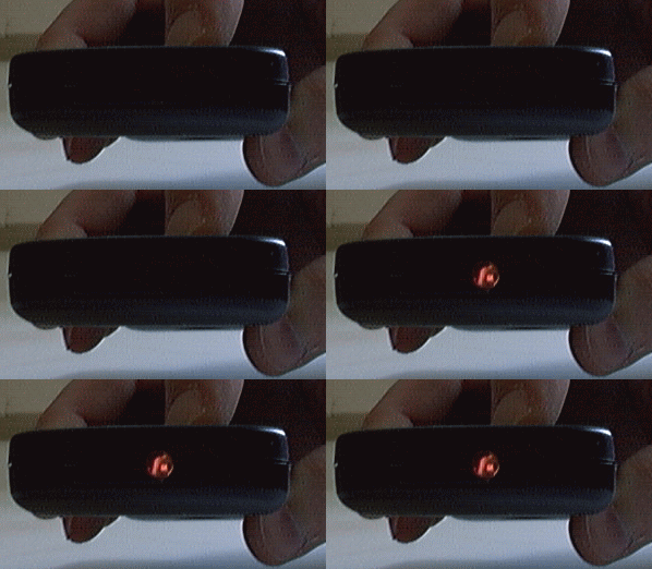
All you have to do is point the remote control towards the lens of the camera, press a button on the remote and look at the monitor.
The flashing light you see in the picture is the actual infra red light the camera recorded. I did manipulate the picture a little so the light can flash in this animated picture. I simply erased the light from the LED during the dark period of the animation. /p>
Be sure the LED stops blinking when you release the key, otherwise you may have a sticky button, which could explain the problems you're having with this remote controller.
Listen To The Rhythm
 The next cheapest solution if you don't own an electronic camera is to listen to the infra red light.
All you need is one IR LED and a pair of high impedance ear phones.
Such an IR LED can come from another old remote control, preferably one that was falling apart anyway so we don't have to feel sorry about it.
If you hold the remote control under test close to the IR LED it will function as a solar cell and generate electricity, which can be made audible by means of a pair of high impedance ear phones.
Unfortunately the solar energy generated by the LED is rather small and can't be used to power most disc man or MP3 player's ear phones.
Measuring a DC resistance of 17Ω the ear phones in the picture aren't really suitable for testing remotes, they are only there for illustrative purposes.
In case you can't find a pair of high impedance ear phones you could also connect the IR LED to the line input of your stereo set. But be careful with the volume, I don't want you to blow up your speakers!
Using An Oscilloscope
I know, this will probably not be the cheapest solution because of the required Oscilloscope. But it takes hardly any effort to create an IR Go / No Go tester if you do own a scope already.
 Using the same technique as above we make an IR LED believe it is a solar cell again.
I've built one in an RCA connector, which can be plugged into an RCA to BNC converter, which then connects easily to the scope.
 If you look a bit closer at the disassembled picture you'll see an SMD type resistor soldered between the two legs of the LED.
This 27kΩ resistor is there to discharge the input capacitor of the scope a bit faster to create nice steep slopes on the screen.
Why 27kΩ you may ask?
Simple, because I had it lying around.
By the way, the LED's cathode should be connected to the ground side of the RCA plug.
The cathode is the one with the form of a little cup inside the LED's plastic shell.
In my case I could generate pulses on the scope with an amplitude of over 0.8 Volts when the remote touches the LED. With this very simple device you can even study the remote control's protocol.
An Active Detector
 Finally I will present an active IR detector circuit.
Such an active circuit has some small advantages over the previous methods.
The biggest advantage is that you can test the remote from a distance instead of having to poke it into the IR LED's eye.
As a side effect it will also produce clearer pictures when connected to a scope.
There's also a slight disadvantage because the circuit requires a modest 5 Volt power supply.
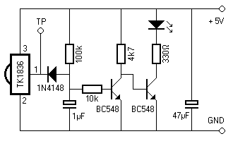
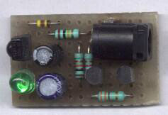
The diagram shows the rather basic circuit. There's not much to it really. The IR signal is detected by the TK1836 (or any other similar detector). When an IR signal is detected it will pull its output low periodically, which will discharge the 1µF capacitor. This is then detected by the first transistor and inverted again by the second which drives the LED output. Since an IR signal consist of pulses the capacitor will not be discharged very long which causes the LED to flicker as long as the IR signal is present.
 I've tested this circuit with different remote controls and it even appears to work with the special ITT protocol when the remote is held close enough.
You can also connect a scope to TP, in which case you are able to study the remote's protocol a little closer.
If you like you can expand this diagram with several IR detectors, each tuned to a specific carrier frequency. That way you can test the functionality of virtually every type of remote control. All you need to do is connect a diode, just like the one in the diagram, to the output of each detector and tie all anodes together.
