IR-Repeater
 Infrared control signals don’t travel well through wooden cupboard doors.
And yet we tend do like to hide all the equipment clutter away from sight in a cupboard, which usually doubles as a table for the TV to stand on.
But how do you control such equipment, when it’s hidden behind a door?
Simple with an IR repeater.
These things can be bought, ready made.
Prices range from acceptable to outright ridiculously high, considering what’s needed to make it work.
For my own personal use I have integrated an IR repeater into my Toslink input selector. However that project is a bit overkill if you only want to use it as an IR repeater. That’s why I’ve built a simpler version of it, which is described on this page.
What Do We Need?
IR control signals usually contain bursts of light, modulated on a carrier with a frequency of 36kHz or 38kHz, the latter being the most common one these days. So basically all we need is a carrier generator, which can generate a 38kHz square wave, which drives the IR LED. Then this square wave must be switched on or of, according to the received input signal.
The Circuit
Generating a square wave with a standard NE555 would be quite easy.
However it requires a few external parts to make it work.
And tuning it to exactly 38kHz may also be a bit challenging.
Keying the NE555 (switching the oscillator on and off) is relatively simple.
However some IR receivers don’t like it when the phase of the 38kHz carrier is not the same between adjacent bursts.
So preferably we should keep the NE555 running all the time and modulate the burst at the output, instead of turning the oscillator on and off all the time.
Generating a square wave with a stupid PIC processor is a lot easier. And the carrier frequency can be tuned quite accurately, without the need for external components. This even adds the possibility to include a status LED, which flashes whenever it receives a signal. This would also have been possible with an NE555, but that might trigger the status LED with every stray pulse of IR light hitting the sensor.

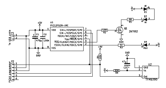
The diagram above shows the entire circuit.
It’s not much.
The circuit is powered by 5V, which can be provided by a USB port of the TV.
If you don’t have a (free) USB port on your TV a USB phone charger may be used.
The power supply to the IR receiver is filtered with a series resistor and a private capacitor.
This is usually a good idea because these receivers are very sensitive.
Noise on the power supply might otherwise generate stray output pulses.
The output of the IR receiver is fed into the PIC processor.
When this output is low the PIC will generate a 38kHz square wave on output GP4, which drives a MOSFET, which can drive one or two IR LEDs.
The circuit diagram shows 2, which is useful if you have equipment on different shelves in your cupboard.
Output GP5 controls the status LED. And that’s about the entire circuit diagram.
How To Program The PIC
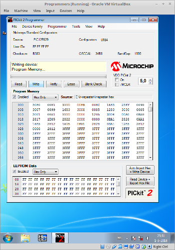
I have simply soldered 5 wires to a pin header, which was connected to the PICKit2 programmer. Easy enough. B.T.W. if programming of the PIC keeps failing you might have to disconnect the IR receiver temporarily. Once the PIC is programmed, these wires were removed again. I don’t expect to need them ever again.
Wait a minute....
I thought you were a Linux user?
How do you control your PICKit2 under Linux.
Well frankly, Linux support for the PICKit2 is not great.
Sad really, but it’s a fact.
So what I do is run a Windows 7 machine in VirtualBox.
This Windows machine is only started when I want to run the programmer.
It is not connected to the internet, so it will never bother me with updates, which will take hours on a Windows machine which only runs maybe once a month.
Not to mention the wasted hard disk space that it will cost.
Officially using Windows like this is not exactly legal.
But I don’t give a ***beeeeep***.
Every time I buy myself a computer I’m forced to buy that useless excuse of an operating system along with it.
And the first thing I do is erase it and install a real OS.
So I have paid more than enough to Microsoft as it is.
Therefore I don’t feel guilty of "illegally" using Windows for 10 minutes a month, on average.
Mechanical Construction

I’ve mounted all the electronics on a piece of pad board 100 x 15mm, just wide enough to have 6 rows of holes.
Three components are placed on the non-copper side of the board, right at the edge.
They are the IR receiver, the status LED and a small electrolytic capacitor.
The rest of the non-copper side of the board remains completely empty.
This will leave a flat surface, which later allow the board to be stuck behind the TV with double sided adhesive tape, with only the IR receiver and status LED poking out from under the TV.
 All the other components, except for the IR LED or LEDs are surface mount devices, which are all placed on the copper side of the PCB.
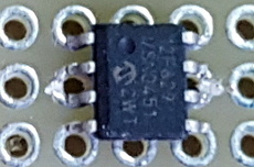
You need to cut 2 holes in half to prevent shorting of the middle pins of the SOIC8 housing of the PIC.
C1 is a low profile tantalum capacitor.
If you keep it all low enough a 1/2 inch wide heat shrink tube will just fit over the entire PCB.
This heat shrink tube should run from just below the IR receiver IC to about 5mm from the other end of the PCB.
Two 3mm holes at the end of the PCB can be used to run a ty rap through, fixing the USB power cable and the LED cable in place.
The ty rap is to be placed just below to the heat shrink tube, because it would make the board too thick to fit into the tube.


The IR LED or LEDs can be mounted in a small piece of PVC cable tray.
Drill a 4.7mm hole in one end and carefully feed the LED through that hole.
Don’t open the cable tray too wide, otherwise it will split right open (this happened to me).
Mounting the LED on the inside of the cupboard door, opposite of the device it needs to control, is very easy, thanks to the adhesive tape on the cable tray.
Download
 Here you can download the software for the PIC processor, which was written in SB-Assembler of course.
The package also includes the circuit diagram.
 I have simply soldered 5 wires to a pin header, which was connected to the PICKit2 programmer.
Easy enough.
B.T.W. if programming of the PIC keeps failing you might have to disconnect the IR receiver temporarily.
Once the PIC is programmed, these wires were removed again.
I don’t expect to need them ever again.
