IR Repeater / Toslink Input Selector
The days of big bulky stereo sets are far be hind us.
After that came the so called surround sets, extremely expensive sets, usually with a poor quality DVD drive with very limited functionality.
No MP3, no XVID or AVI playback and they were very picky about what DVDs they would play.
A cheap no-brand DVD player costing 20 times less could play anything you threw at it, without any problems.
I know, I've owned both categories.
Therefore I now have decided to buy a simple amplifier/speaker system, which would basically last a life time.
It would have to play from 4 different sources: The digital TV recorder, a blue-ray player (a cheap no-brand one of course), a computer or media player and the TV-set itself.
Unfortunately the amplifier/speaker system I had in mind only had one digital and one analog audio input, which obviously is not enough.
So I went looking for a digital Toslink input selector.
Much to my surprise there is/was very little choice.
The only thing I could find was a passive input selector, which would switch the fiber path from one source to the other with a rotary switch.
It had only 3 inputs and it was manually controlled.
This means, there was no remote control and it was one input short from my requirements.
On the other hand, after buying a new flat screen LED TV for the living room I had decided to place all equipment (digital receiver, blue-ray player and media computer) in Harry Potter's bedroom, which is right behind the wall the TV is hanging from. So I needed an infra-red relaying device, which would carry the infra-red remote signals from the living room into the cupboard under the stairs. They do exist in several flavours. However much to my surprise they were all quite expensive. I could build one for about €10 while the cheapest ready made one I could find would cost about 7 times as much.
After a short consideration I decided to combine the two functions (Toslink input selector and infra-red relay) into one device.
This makes the infra-red relay function a bit more complex than absolutely necessary, but it would automatically enable me to build in an infra-red decoder to select one of the four digital audio inputs remotely.
And thus this Ifra-red relay / Toslink input selector was born.
When I came home with my brand new powered speaker system there was one little snag though.
I had bought it with a special offer, which included a free blue ray player.
Nice, I didn't have one yet and it was on my wish list anyway.
Alas, the blue ray player was a Philips.
And Philips is, to my knowledge, the only company in the world which still uses coax cables to transport digital audio.
The rest of the world has chosen for optical interfaces ages ago, but Philips still haven't.
Therefore I couldn't connect my blue ray player to my input selector.
Why they offer a free Philips blue ray player with a set with only an optical digital input is beyond me.
Because of this I had to add a small extra circuit, which converts digital audio signals over coax to optical signals again.
This is not too difficult, however finding a place on the rear panel of the switch box to accommodate for the coax input was a bit of a challenge.
The Circuit
The circuit can be broken down into a few functional parts:
- Infra-red input
- Infra-red output
- Digital audio input selector
- Front panel control
- Micro controller
- Power supply
The entire circuit diagram is included in the download package, which can be found at the bottom of this page.
Infra-red Input
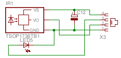 The infra-red input is nothing more than a simple integrated receiver, which is placed close to the TV.
I have glued its PCB behind the TV, with the IR receiver just sticking out from under the TV so it can see the signals sent from the couch.
In my case I only need one input receiver which is tuned to a carrier frequency of 38kHz.
The Philips blue ray player operates with a 36kHz though, however I have no problems with that over a distance off 5 meters from couch to TV set.
If you can't cover the required distance you may decide to add a 36kHz and/or a 40kHz in parallel with the 38kHz receiver.
In addition I have placed a small LED next to the infra-red receiver, which can signal the reception of IR commands for some visual feedback.
Infra-red Output
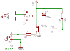 The infra-red output is even simpler, consisting of a transistor driving an infra-red LED.
Just about any infra-red LED will do.
Mine came from an old obsolete remote control.
In my case I needed only one single LED, which is placed in the cupboard right across the equipment.
The distance between LED and equipment is approximately half a meter and is always free from obstructions.
The dimensions of the parts are set to send short 100mA pulses through the IR-LED which is more than enough to get reliable communication over such a short distance.
If your situation can't guarantee a free line of sight from the IR-LED to all the equipment you may want to change the output to allow one IR-LED per device you want to control.
Then you can stick each IR-LED on the front panel of the devices, immediately above the device's IR-receiver.
This is simply done by increasing R7 to allow about 10mA through each IR-LED.
You can use a separate R7 for each IR-LED you need.
Digital audio input selector
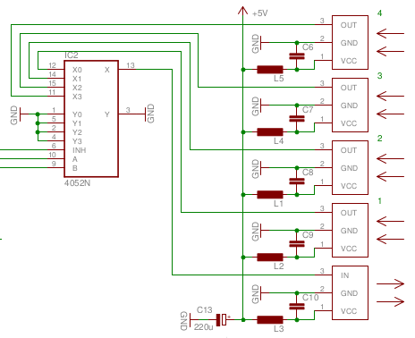 The input selector consists of 4 integrated Toslink receivers, one integrated Toslink transmitter and half of a dual 4-to-1 input selector.
All receivers and the transmitter are supplied with DC 5V, which is filtered by LC filters.
In my case I used integrated LCL filters, which I have salvaged from scrap equipment.
Apart from the power and ground pins the final pin of the Toslink receivers is a TTL level output pin.
I have used Farnell part number 1243861 for these receivers.
The integrated Toslink transmitter is very similar to the receivers.
The only difference is that the third pin is a TTL level input instead of an output.
Mine came from a scrapped device.
Warning: Be careful, the pinning of these devices is not standardized among different manufacturers! I have fried one receiver because I mistakenly assumed the pinning of the transmitter and the receivers would be the same. So always check the pin numbers of your devices in the appropriate documentation.
All four inputs are connected to one half of the dual 4-to-1 selector, a CD4052. Only one of the inputs is connected to the Toslink output at any given moment, selected by the 2 select pins. An inhibit pin will cause all inputs to be isolated from the output, which is virtually a mute function. I use this mute function to avoid glitches in the output sound while switching inputs.
Front panel control
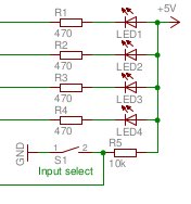 A total of 4 LEDs will tell the user which one of the inputs is currently connected to the output.
A push button is used to step through all 4 inputs in sequence.
Every time the push button is pressed, the next input is selected.
Micro controller
The processor used is an ATMmega 88 from Atmel, which may be a bit over kill for such a small project.
I could have used just about any other controller, but this one was close at hand when I started the design and it's very cheap.
I could have used a PIC processor too (for instance the PIC12F629), but recently I was put off again by the pitiful Microchip IDE while building a very simple project at work.
With an Atmel processor I can use my own SB-Assembler, which makes program development a whole lot more fun, for me.
The controller has all ingredients it needs built in.
The only thing we need externally is the programming connector, if you want to program the processor in circuit.
During development this is very much desirable.
If you want to copy the project as is, you might as well omit the programming connector if you can program the ATMega 88 on an STK5000 or something similar.
The rest are simple I/O lines.
None of the used I/O pins require special features.
Coax to IR converter
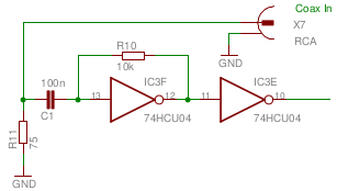 This is the little circuit I had to add because of the stupid Philips blue ray player we got as a special offer with our powered speaker set.
It converts the digital audio from Coax to normal TTL pulses which can be fed to the Toslink output driver, to create an optical output again.
One inverter of the 74HCU04 is used as an analog amplifier.
The gain of this amplifier is rather high and produces nice square waves on its output.
The second inverter corrects the phase of the signal and takes care of some extra pulse shaping.
The output of this circuit is fed to input 3 of the input selector switch.
A jumper allows me to select between the original optical input and the coax input.
I only needed one coax input.
The 74HCU04 has four more inverters, which can be used to add two more Coax in to optical out converters if you need them.
If you don't need them it's best to tie their inputs to ground, to reduce power consumption.
Power supply
I simply use an USB connector to apply the required 5V to the system. Any cheap USB charger will be more than sufficient to power the device. The entire system draws less than 10 mA while idle. And it will draw a few short bursts of 100mA pulses while relaying the received IR pulses.
Software
Here is a list of all the tasks the software has to perform:
- Show currently selected input on the front panel LEDs.
- Monitor the front panel button.
- Mute the output for about 0.1 second when switching to a different audio input.
- Create short bursts at a rate of 38kHz on the IR output as long as the IR input is low.
- Flash the LED next to the IR receiver whenever an IR signal is received.
- Decode some IR commands, which select one of the four audio inputs
The software is included in the download package which can be found at the bottom of this page.
Show currently selected input
Showing the currently selected input on the front panel is no rocket science.
Simply one of 4 LEDs is switched on, while the others are all off.
I use a look-up table to get the LED pattern and the input select states for any one of the 4 different inputs.
At the same time the mute is activated and a timer is started, which will eventually clear the mute state.
Having all LEDs, the input select pins and mute pin on one and the same output port helps in keeping the code compact.
Monitor front panel button
Monitoring the input key is not difficult either.
A counter is incremented at a rate of 38kHz as long as the key is down, with a count limit of 255.
The counter is reset to 0 when the key is released again.
The key is accepted when the counter reaches a preset value of 190, which equals to about 5 ms.
This effectively eliminates key bounce, which would advance the input selector more than one input per key press.
As soon as the key is accepted the mute function is activated, the appropriate LED on the front panel is switched on and the next audio input is selected.
Mute output during switching
The mute time is measured by a counter, which is preset as soon as the mute function is activated. This counter is decremented at a pace of 38kHz until it reaches zero. When it reaches zero the mute is removed and the down counting of the mute counter is stopped.
Infra-red carrier
Timer/counter2 of the ATMega 88 is used to generate an interrupt at a rate of 38kHz, which in my case is the required Infra-red carrier frequency.
All actions of the processor are synchronized to this clock.
This greatly simplifies the implementation of all the functions the controller has to perform.
Each time the interrupt is generated a new pulse may or may not have to appear on the IR output.
If the output pin of the IR receiver device is low, the pulse with a length of 1/3 of the interrupt repetition time is generated on the IR LED output.
Both compare registers of Counter/Timer 2 are used to generate the 38kHz carrier frequency.
Compare interrupt A starts the main routine.
If the IR input is low it will drive the IR-LED output low too, if the IR input is high the IR-LED output remains high.
The compare A interrupt will also reload timer 2 with its preset value, which determines the 38kHz frequency.
All that compare B interrupt has to do is to set the IR-LED output high at about 1/3 of the pulse width.
Unfortunately this interrupt has a lower priority than the compare A interrupt.
Therefore, theoretically it may happen that this interrupt is triggered a bit later, when interrupt routine A runs longer than 1/3 of the pulse width.
This is rarely the case, if ever and will not likely disrupt the infra-red relay reliability.
This procedure effectively remodulates the received input signal on a 38kHz carrier, just as it used to be when the signal left the remote controller.
Most IR protocols use a 38kHz carrier these days.
Some use 36kHz or 40kHz instead.
I don't expect big problems if you own devices which expect 36kHz or 40kHz modulation.
In worst case the control distance will be a bit shorter.
Usually for an IR relay device this distance is not so important anyway, 1 meter will do most of the time, which should easily be covered even with a carrier which is slightly off center.
Flash the feedback LED
Flashing the LED next to the IR receiver to signal IR activity is quite easy.
To avoid stray flashes the software turns the LED on if the IR lead pulse has been received.
At the same time a counter is preset with a value which will count down to zero when decremented at a pace of 38kHz.
Each time a pulse is received the counter is preset to this value again.
The LED is turned off as soon as the counter is allowed to count down to 0.
Some Infra-red protocols don't send a long pre-pulse (Philips again) and will not flash the LED.
For me this is not really a problem.
Usually I am well aware when I press the buttons on my remote.
Decoding IR commands
Decoding IR signals which are used to select one of the 4 inputs using the remote control is the most difficult task the controller has to perform.
In my case I needed to decode some signals coming from my universal remote, preset to the Bose protocol.
The decoding principle is based around a state machine.
I have explained the operation of a state machine in a separate chapter.
The Bose protocol I wanted to use was basically the extended NEC protocol.
I had a little problem getting the commands right though.
None of the digit keys are used on the Bose speaker set, so I could use the digits 1 to 4 to select the Toslink input.
However finding the proper commands proved a bit difficult.
It appeared that the remote sent a few different commands per key press.
I finally decided to output the command on PORTD during debugging for each key pressed, so I could use an oscilloscope to find the command values.
This proved the easiest way of finding the codes.
If you look at the source you will find that the codes I have found are not very obvious, but they work, and that is what we are here for.
If you need to decode a different protocol, or if your remote sends different addresses and commands you'll have to reprogram the IR receiving routines. You are on your own there, because it is fairly impossible for me to help you with that. Reading the source should give you a rough idea of how to handle this job though.
The Build
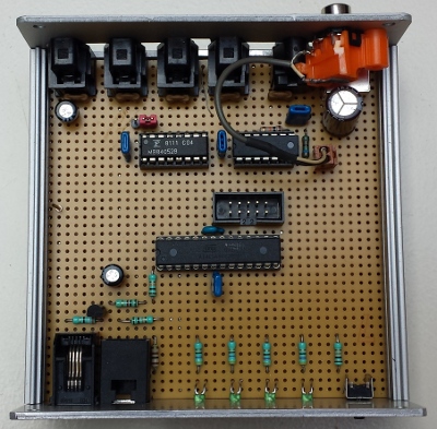
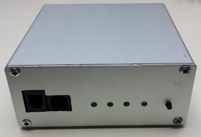
I have a few little aluminum boxes, saved from scrap. As you can see the circuitry fits in easily. Unfortunately the same can not be said about the connectors at the back. The back panel space is rather limited. It could however easily fit 4 optical input connectors, an optical output connector and a USB type B input connector for power. Later I had to add a coax input to accommodate the stupid Philips blue ray player. Fortunately there was just enough space left for that.
 The front panel holds, apart from the 4 LEDs and input select button, two connectors.
A 4 PIN RJ-11 connector, which goes to the Infrared output LED.
And a 4 pin RJ-12 connector, which is used to connect the infra-red input receiver and a feedback LED.
The picture on the right shows the jumper, which allows me to chose between an optical or Coax input for Input 3.
The brown components in front of the IR inputs are integrated LCL filters.
I have no idea where to buy them because I've got mine from scrap.
You can however replace them with separate chokes and capacitors.
Download
 And now the moment you have all been waiting for, haven't you?
This download contains the total circuit diagram, the assembly source code, the hex code for the ATMega 88 controller and some fuse files.
The last are not absolutely necessary, but you may need them if you want to use a micro controller which has non standard fuse settings.
If you want to make some changes to the program you can use my SB-Assembler to assemble the source file.
However if you prefer to use another assembler you may have to change a few lines in the source code.
Usually your assembler will tell you which lines it doesn't understand.
