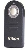
Nikon IR-Remote Control
A few months ago one of my visitors gave me an idea for a new small project, an IR remote control for my Nikon DSLR camera.
Not that I absolutely need one, surely I don't need it bad enough to get one for about €30 or €40 from e-bay.
However it would make a nice little in-between project.
Big Mike explains the very easy protocol used by the original Nikon remote controls ML-L1 or ML-L3 on his web site.
The site also shows some existing DIY projects for a remote.
I happen to be very good at re-inventing the wheel, therefore I have designed and built my own version.

It just so happens that I've bought myself an ATMEL STK-500 kit, so this was a perfect test case for it.
I've ordered some samples of the ATtiny13 processor from Atmel, which can be operated without external clock.
Even this small processor is a bit of overkill for the job at hand, but this was the smallest processor I could find.
On the above mentioned web site there are some pictures of other people who have built their own versions of an IR remote control in several different appearances.
Personally I think building the remote control in an empty tic-tac box is a great idea!
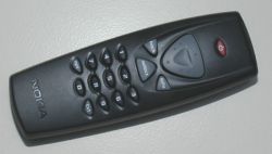
However I've chosen to build it in an obsolete existing remote control.
Simply because it was at hand and because it can hold two standard AAA batteries.
I've rewired the switch matrix in such a way that I now can press any of the keys to fire the shutter.
Feel free to use your imagination if you want to build your own version of the IR remote control.
There is no PCB for this easy design.
In my case the output amplifier was already available in the existing remote control.
I've only removed the original IC from the board and added the ATtiny13.
Collecting The Facts
I don't have the original specification of the Nikon remote control protocol. The information on Big Mike's web site was also derived from reverse engineering. What I understand from that information is that the timing of the signals is not particularly critical. Therefore I have taken the liberty to adjust some of the times in the waveform to match exact multiples of one clock period of the 38kHz carrier, which is 26,3µs.

This diagram shows the timing of one half of the command. The second half is exactly the same and is repeated 63.2ms after the first command.
The bursts are modulated on a 38kHz carrier.
Care has been taken to keep the phase of the carrier between the bursts as constant as possible in order to achieve the optimal sensitivity of the IR receiver in the camera.
In my case I could fire the shutter even at a distance of about 12 meters.
It probably reaches even further, but that's as far as could get away from the camera without getting wet from the rain outside.
The Software
The software consists of only two subroutines, one of which is carefully designed in order to generate precise timings.
Well, as precise as they can get of course if you consider that the internal RC oscillator of the ATtiny13 can deviate from the nominal frequency by as much as 10%.
I have run some tests by deliberately altering the timing, without any problems.
I have also tried 2 other ATtiny13 processors and they gave exactly the same results.
Therefore I doubt that you'll ever have to adjust the timing of the burst routine.
The SENDBURST subroutine consists of a main loop which always takes 26.3µs to execute.
Wait, I tell a lie!
Not always, the first time through the loop is a bit shorter to compensate for the subroutine call and return overhead.
Please note that SENDBURST is the entry point of the subroutine.
The subroutine is the same for marks and for spaces.
The LEDSTAT register indicates whether we're sending a mark of a space.
A value of 0b11111101 will leave the LED extinguished, while a value of 0b11111111 will turn the LED on/off at a frequency of 38kHz.
;-------------------------------------------------------------------------
;  Send BCOUNT pulses.
;  BCOUNT   : Holds number pulses to send
;  BDELAY   : Holds high/low delay times
;  LEDSTAT  : Holds mark (11111111) space (11111101) flag
;-------------------------------------------------------------------------

NEXTPULSE:  LDI     BDELAY,BURST0   ; Reload delay counter for Low period
SENDBURST:  DEC     BDELAY          ; Low period delay loop
            BRNE    SENDBURST
            NOP                     ; Fractional compensation
            OUT     PORTB,LEDSTAT   ; Set or Clr output bit
            NOP                     ; OUT is one cycle, SBI was two
            LDI     BDELAY,BURST1   ; Reload delay counter for High period
BURSTLOOP:  DEC     BDELAY          ; High period delay loop
            BRNE    BURSTLOOP
            CBI     PORTB,1         ; Clr output bit
            DEC     BCOUNT          ; Decrement burst pulse counter
            BRNE    NEXTPULSE       ; Do until all pulses are sent
            RET
Normally the CPU is in deep sleep mode, in order to save battery power.
When a change occurs on the PORTB0 pin the CPU wakes up.
An interrupt routine is started, however the contents of it are empty.
Immediately after returning from the interrupt routine the two IR commands are transmitted.
Both commands are separated by a 63.2ms gap.
After both commands are sent the CPU enters a loop for as long as the remote button is pressed.
Once the button is released the CPU enters deep sleep mode again, waiting for another key press, which will repeat the entire sequence once again.
During normal operation the AVR draws about 1mA (not counting the current through the LED of course).
In deep sleep mode the current consumption of the entire circuit drops to about 0.2µA.
Add some initialization in front of this all and the program is ready. Before I forget to mention it, the internal RC oscillator runs at 9.6MHz. By default this frequency is divided by 8, which is a good choice if you're talking energy saving. However it appeared that it was hard to derive a good enough 26.3µs cycle from this frequency. Therefore I've decided to change the clock division ration to 4, which will give an almost perfect 26.3µs cycle.
Feel free to download the assembler source file and hex file here. I have used Atmel's Studio 4 development tools instead of my own SB-Assembler for a change, just to get the feeling of it. How I missed my local labels in a short program as this already!
The Hardware
 Let's start with the circuit diagram.
Nothing much to tell here.
Basically its only the ATtiny13 with a little output amplifier.
In my case all parts were already on the PCB of the donor remote control, which was an obsolete remote controller for a Nokia satellite receiver 210S.
The only change I've made is R1 which originally was 27Ω.
I noticed a slight drop in output amplitude from the CPU, so I decided to increase the resistor to 47Ω.
This still gave me a maximum control distance of more than 12 meters.
I don't know the type of the SMD transistor used here.
Judging by its task I would say it is a low gain, high ICE NPN type of transistor.
If you don't need such a long range you might as well connect an IR LED between +3V and PB1 with a series resistor of 100Ω. I haven't tested the maximum range for that configuration, but I believe it should still be at least one meter, which is sufficient if you want to use the remote control to fire the camera without touching the camera.
 This pictures shows the PCB of the donor remote controller with the modifications I've made.
The only new component is the processor, which hangs off of the bottom of the PCB.
It neatly fits in a cavity in the casing as if it has always been intended for this purpose.
It goes without saying that I've removed the original IC from the PCB first.
OK, I'll admit that the donor remote control has too many buttons for this task. But this was for me the easiest way to build the project. All necessary parts are there, buttons, battery holder, output amplifier, filter capacitors, nice case which needed no filing. What more do I want?!
Using The Remote
 Before you can use the remote you'll have to select the remote, or timed remote mode on the camera.
Then it's only a matter of pointing the remote to the little eye of the camera, which in my case is just above the D70 logo, and press the button.
If you're close enough to the camera you may even fire the shutter when standing behind the camera, for as long as there is enough reflecting surface available in front of the camera.
Please note that the camera will shut down after 15 minutes of inactivity. So if you need longer intervals than that, make sure to fire it occasionally.
Pentax Remote
Someone pointed me to this information regarding the remote control protocol for Pentax DSLR cameras.
My program is easily adaptable to work on Pentax cameras instead of Nikon.
You could even teach the program to emit both protocols, one after the other or triggered by different keys.
I don't have a Pentax camera myself, therefore I am unable to verify the information.

All bursts are made using a 38kHz carrier signal.
