Constant Current Sink
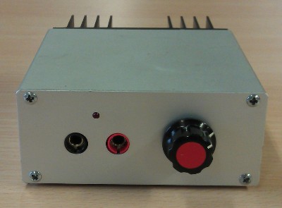
A constant current sink is the opposite of a constant current source. Over the entire specified input voltage range, the current drawn by the device will remain constant. The constant current sink I present here is a simple device, which needs no external power. It can sink constant currents of 100mA, 200mA, 500mA or 1A, selected by a rotary switch. Officially the minimum input voltage is 4V, but in reality the current remains constant down to an input voltage of 3.6V. The maximum input voltage is 35V as long as you provide adequate cooling for the LM317. With moderate cooling of the LM317 the maximum input voltage is well above 15V at 1A sink current.
There are many situations where you may need a constant current sink device.
Personally I use it quite often, mainly to measure low ohmic resistances and the capacity of rechargeable batteries.
If you discharge a battery with a constant current you can simply monitor the voltage over time in order to determine the battery's capacitance.
A battery which can provide 1A during 120 minutes has a capacity of 2Ah for instance.
Be careful though to switch off the constant current sink when the "empty" level is reached, otherwise you may damage the battery.
Measuring low ohmic resistances is done by sending a known current through the unknown resistor and measure the voltage across the resistor.
This is easiest with a constant, known current, in this case 1A.
Every mV drop across the unknown resistor yields 1mΩ of resistance.
Be sure though that the resistor under test can withstand a current of 1A, although low ohmic resistances usually can.
Specifications
| Input Voltage range | 4V .. 35V (provided adequate cooling) |
| Constant currents | 100mA, 200mA, 500mA or 1A ± 2% |
Circuit Diagram
The circuit diagram below shows the entire circuitry of the constant current sink. In the heart of the circuit is the LM317. This is an adjustable voltage regulator, which can easily be converted into a constant current source. I've picked the LM317 because of the low and accurate output voltage. This will lower the minimum input voltage, which would be a lot higher should I have used a standard voltage regulator.
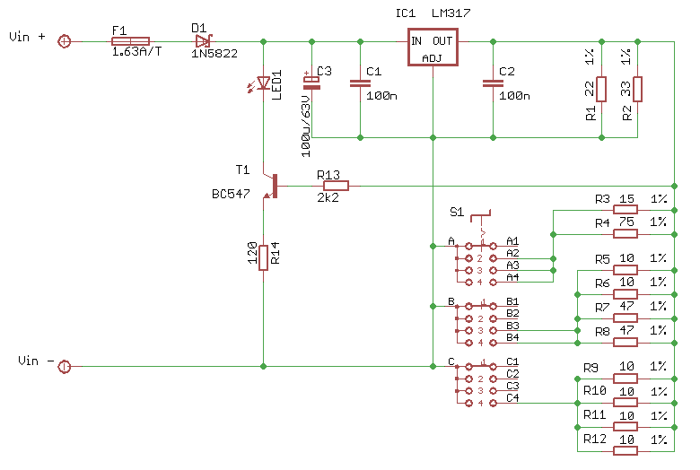
The voltage between the OUT and ADJ pins of the LM317 is held constant at a precise value of 1.25V.
If you put switch S1 in the 1 position, none of the resistors R3 to R12 are connected, so let's ignore them for a moment.
The only load the LM317 sees now are the resistors R1 and R2.
This load will result in a current flowing through the LM317 of 95mA, which is just 5mA short of 100mA.
That's where the current source around T1 comes in, to add the missing 5mA.
The voltage across R14 is a constant 1.25V - 0.6V junction voltage, is 0,65V.
This creates a constant current through R14 and the LED1 of 5mA, which will light whenever the circuit is operational, adding the missing 5mA in the process.
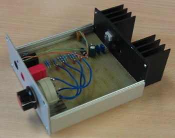 When the switch S1 is put to position 2 the resistors R3 and R4 are added to the load seen by the LM317.
This extra load is exactly 100mA.
Add the original load to that and you'll get a constant current of 200mA when S1 is in position 2.
It shouldn't be a surprise to find that the resistors R5 to R8 will give an extra load of 300mA, on top of the 200mA we've seen so far. Thus with S1 in position 3 we get a total constant current of 500mA.
Need I explain that R9 to R12 will result in an extra 500mA load, which will sum up to a total of 1A when S1 is set to position 4?
I was surprised that it was so easy to create these currents with just standard resistor values.
I didn't even have to make any adjustments to get the accuracy of the selected currents all well below the intended 2% deviation margin.
You can, if you wish, fine tune the sink current by adjusting R14 a bit.
I was able to increase the accuracy to below just 1% by decreasing R14 to 100Ω.
Keep in mind though that changing R14 changes all current ranges at the same time.
Finally D1 adds protection against reverse polarity errors. I have used a Schottky diode here, which has a lower junction voltage of just about 0.3V, which decreases the negative effect on the minimum input voltage. In my case the minimum input voltage is 3.6V. When the input voltage drops below that the sinked current will no longer be constant, meaning that the current will drop the lower the input voltage gets.
Applications
Measuring battery capacity.
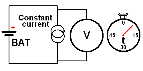 Measuring the capacity of a battery is quite simple.
Draw a constant current from a fully charged battery until its empty threshold is reached.
For normal NiCad or NiMh batteries this threshold is 1V per cell.
For LiOn batteries the threshold usually is 2.5V per cell.
Be sure not to discharge the batteries below the empty threshold, especially LiOn batteries are very sensitive to deep discharges and are easily damaged.
Warning! This circuit does not shut off automatically when the battery is discharged.
You'll have to do that manually.
In this diagram you see the setup for a simple battery capacity test circuit.
On the left you see the battery under test.
Simply connect the constant current sink device and a Volt meter both in parallel to the battery.
A simple clock can be used to measure the time it takes for the battery to drop below the "empty" threshold.
Multiply the number of minutes it took for the battery to discharge with the preset constant current, divide that by 60 (minutes per hour) and you've got the battery's capacity in Ah.
Measuring low ohmic resistance.
 Ohm's law is the first thing you'll learn if you study electricity.
It shouldn't be a surprise that we're going to use Ohm's law to determine the value of an unknown low ohmic resistor here.
The resistance can be calculated by dividing the voltage drop over the resistor by the current through the resistor.
For this we use a voltage source and a constant current sink.
Both could be built into a standard lab power supply, but what if you're outside in the field, where there's no mains power to operate such a power supply from?
Then you can use a battery, which should be powerful enough to supply a current of at least 1A for the duration of the measurement.
And we'll need our Constant Current Sink device.
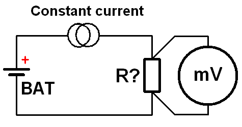
Connect everything according to this diagram.
The battery, the constant current sink device and the unknown resistor are all connected in series.
Select a constant current of 1A, if the resistor can withstand that current.
Most low ohmic resistors can.
Now every mV dropped across the unknown resistor equals to 1mΩ.
Thus if the mV meter reads 12.3mV, your unknown resistor is 12.3mΩ.
Be sure to measure the voltage across the unknown resistor as close to the resistor itself as possible.
This eliminates the error introduced by the resistance of the current carrying wires of the circuit.
