Automated Awning Control
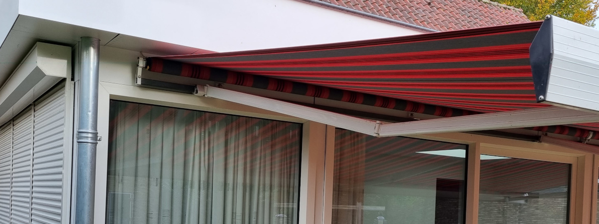
In our new house the awning had to be deployed manually.
Fortunately it was already motorised, but we had to hold a button for about 1 minute to fully deploy or retract the awning.
Needless to say that operating the awning when we're not at home was completely impossible, let alone automating it.
About two years ago I managed to find some time to throw together a small circuit, controlled by a Raspberry Pi Zero W, which can now control the awning.
Manual control is now done with the push of a button, no need to hold that button for up to one minute any longer.
Remote control is done through MQTT.
This takes away the required intelligence from the controller.
Automation is done through Node-Red.
This allows for complete automation and remote control through a web interface.
This setup has worked flawlessly during the long and hot summer of 2022.
The automated awning managed to keep the house relatively cool.
It was still warm inside, but hey, it's not an aircon.
Temperatures were quite bearable that year, thanks to the awning.
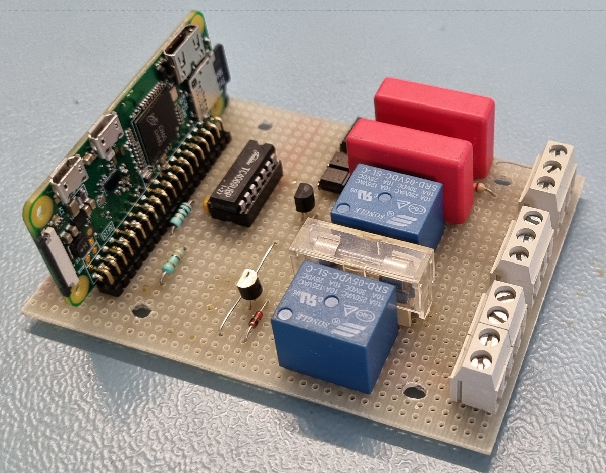 Awning controller mark I
Now the summer's over and we don't need the awning anymore for a while, it's time to make some modifications to the circuit and software.
I later realised that the shutters on the side of the conservatory can also be used to regulate the in house temperature during summer and winter.
Therefore the controller needed two more outputs.
This also opens up the opportunity to make an SB-Projects project out of it.
Requirements
Manual control of the awning must still be possible with the original buttons, preferably without rewiring.
And original manual control should be possible when the controller is disconnected all together.
I can simply disconnect the controller, put two connectors together and I end up with the original configuration.
The two buttons then simply power either the up or down side of the awning motor.
This means that when a button is pressed 230V AC is applied to the controller's input.
Needless to say that we need a safe interface for that.
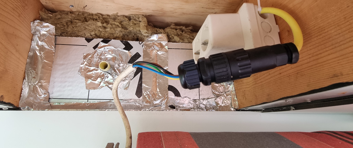 Original operation is still possible by simply connecting the input and output connectors together.
Four relays are required to control both the awning and the shutter motors.
Each motor simply requires 230V AC to be connected to either its up or down input.
Each motor will disconnect its input automatically when it reaches its extreme position.
Thus it is sufficient to just time the duration of the movement and add a few seconds to that as an extra margin.
Current consumption is less than 1A for both motors.
An MQTT client should run on the controller. This MQTT client can then publish its current status and subscribe to commands originating from Node-Red in my case.
And let's throw in a thermometer or two, just because we can.
One thermometer simply measures the temperature of the location where the controller is mounted.
The other one can measure the temperature above the ceiling of the conservatory.
Both temperatures are published to MQTT with a 15 minute interval.
And perhaps I might stick a strip of NeoPixels to the face of the awning one day. So let's prepare for that too.
Hardware
The heart of the controller is of course the Raspberry Pi Zero W. This allows the controller to connect to my WiFi. The program for the Raspberry Pi was written in Python.
 The two button inputs are driven by the original 230V push button on the wall
The button inputs are activated by applying 230V AC to them. A typical RC current limiting circuit drives 2 cross polarised LEDs of two opto-couplers. The outputs of these opto-couplers are connected together and buffered by a capacitor. This output goes low when 230V AC is applied to the input.
At first I used 2 mechanical relays, obtained from China. But these relays were relatively bulky and occupied a considerable amount of space on the PCB. It simply was physically impossible to add two more for the shutter control. So I decided to use solid state relays instead. A ready made PCB, containing four solid state relays was soon ordered from China. Controlling these relays is simply a matter of applying a high logic level to appropriate inputs of this module. Each relay has its own axial 2A fuse.
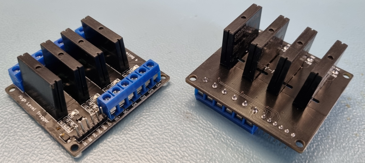 The original module on the left. The relays moved to the bottom side on the right.
I applied a few modifications to this module.
I did not have room enough to mount the relay PCB flush to the main PCB.
I had to elevate it, even above the two big input capacitors.
This meant that the solid state relays would stick out high above the enclosure.
That's when I came up with the bright idea to mount the solid state relays on the bottom side of the PCB.
The relays are about the same height as the input capacitors anyway.
Simply turning the relay PCB upside down was no option, because that would make the screw terminals inaccessible.
And I have replaced the input header with a 6-pin connector.
This would make it easier to wire the thing up to the main PCB.
Finally I have also bridged one side of all the relays together.
This bridged side is later to be connected to the Live terminal of the 230V input.
Connecting 2 thermometers is rather simple, thanks to Dallas Semiconductor's 1-wire protocol. B.T.W. One of the thermometers is located on the main PCB, the other one is external and is pushed through a hole in the wall, which ends up above the ceiling.
![]() The NeoPixel driver should eventually drive the string of NeoPixels along the front face of the awning.
The NeoPixel driver should eventually drive the string of NeoPixels along the front face of the awning.
And finally there is a driver for the NeoPixels. Normally the Raspberry Pi could drive NeoPixel LEDs directly, despite the fact that it only outputs 3.3V instead of 5V. However there will be a wire of about 3 to 4 metres between the controller and the first NeoPixel LED. I think that would be too much to be driven by the Raspberry Pi directly. Hence the addition of the driver.
O, and there is of course the power supply, which is nothing special. As long as there are no NeoPixels to be driven, a simple 5V phone charger is more than capable enough to power the whole thing. If NeoPixels are to be connected, the power supply must be able to support the entire string of LEDs. A simple phone charger will no longer suffice then, I'm afraid.
The 230V connection for the motors is connected to two 3-way screw terminals, one for Neutral wires and one for Earth wires. The Live wire is directly connected to common rails on the screw terminals of the relay PCB.
 The complete circuit diagram. Click on the picture to download the PDF file.
Glueing It All Together With Node-Red
Like I said, the awning and shutter are controlled through MQTT. That way a central computer, running Node-Red, can combine several input conditions to determine whether the awning or shutter should be deployed or not. A few different input signals are used in order to make the right decisions.
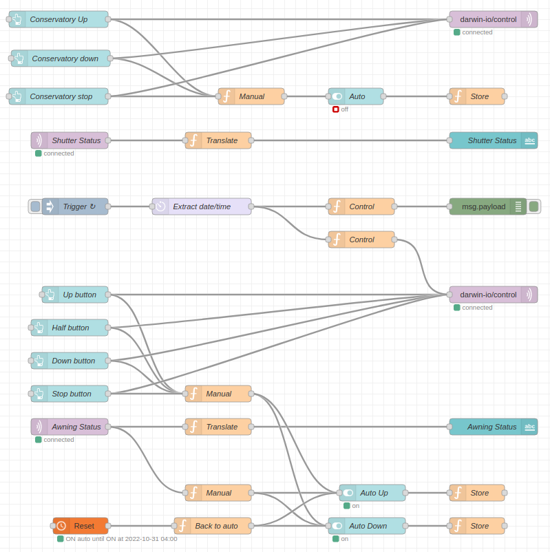 This is what my Node-Red flow looks like. The shutter controll is not automated yet.
In our situation the conservatory is facing South-East, which means that its entire 8 metre wide window is exposed to the sun until 2 PM.
After 2 PM the awning is retracted automatically because it has no purpose any more.
Normally it is beneficial when the sun helps to heat up the house.
During summer months however it can be a bit too much.
Therefore I will only allow automatic deployment of the awning if the temperature inside is 23 C or higher.
This temperature is measured by our thermostat, which publishes the internal temperature over MQTT every 5 minutes.
And I only need to deploy the awning when the sun is shining of course.
It's no use to deploy it when it's raining.
For this I use the output of our solar PV installation, which is published every minute over MQTT.
If the moving average over the past 15 minutes exceeds 2 kW we can safely say that the sun is shining and we should deploy the awning.
A 10% hysteresis is also added, so the awning is only retracted when the 15 minute moving average drops below 1.8 kW.
This has proved to be a good workable solution.
You don't want the awning to be deployed when it is raining, and you don't want the awning to go up and down every time a small cloud covers the sun.
Finally I'm probing the API of a local weather station which publishes the reported wind speed every 5 minutes, among other weather related properties, through MQTT. If the wind speed is 8 m/s or above the awning is retracted, no matter what. Even when I had deployed the awning manually.
Whenever I control the awning manually, either locally, or via the web interface, the automated process is halted for the rest of the day. Otherwise the controller might contradict my decisions.
The side window of our conservatory is getting some sunlight during the afternoon.
So during summer months it would be best to keep the shutter down during the afternoon too.
The rest of the time it can be up.
During the colder times of the year it would be best to have the shutter open during the afternoon, when the sun is shining.
This may help heating up the house, even if it's only a marginal bit.
During the rest of the day the shutter is best kept closed, to create a better isolation.
Perhaps you have already noticed that I'm quite a fan of MQTT.
Thanks to MQTT you can connect many different, otherwise unrelated, devices together in order to make some educated decisions.
In my case Node-Red makes the decisions, but you can use any programming language or platform you like.
I hope I've given you some interesting ideas with this project, in case you want to automate your own awning or shutters.
I have only mentioned what decisions the software has to make, without showing any detailed source codes.
Anyway, your personal situation is likely to vary too much anyway, which would make my personal implementation less suitable for you.
Send me an email if you're interested in the software for the Raspberry Pi.
I'll be happy to share it with you.
Photo Galery
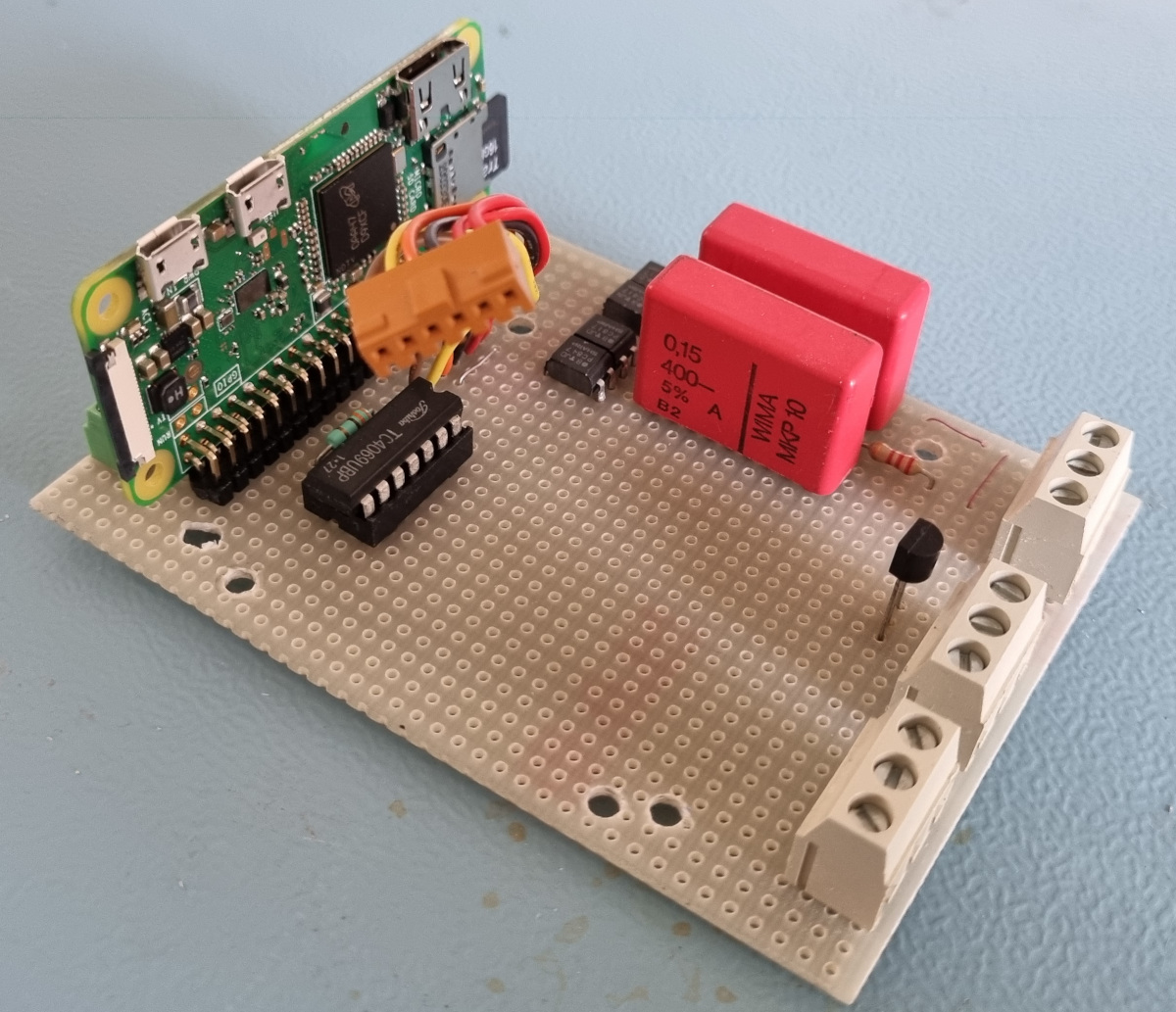 Awning controller Mark II, without the relay module.
 The complete module.
 The bottom side showing the wiring. Some pads are removed to create a bigger distances for the higher voltages.
 Home sweet home. The project box is held up by a magnet, stuck to a metal plate, which makes it easier to remove.
