My YC-355D
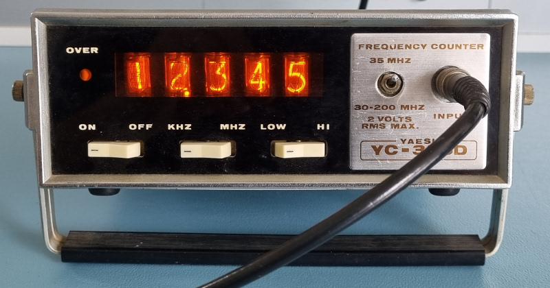 Spoiler alert, I managed fixed it
Have I told you that I love equipment with nixie tubes? I already owned two nixie DMMs, but I didn't have a nixie frequency counter yet. It's not that I desperately needed one, therefore I let some of them pass on our Dutch Ebay clone Marktplaats because I don't want to pay too much. And I don't want the counter to be too big either. The big ones usually have a loud fan in the back, so I let those pass too.
At some point I've payed for a nice little HP 522B counter, which was never delivered.
It appeared that the seller was a mentally unstable person with severe cash problems.
I hope she did spent my €30 well.
And then I found this counter.
Alas it's not an HP.
I had never even heard of the brand Yaesu before.
According to the seller the nixie tubes worked, but the counter had some issues with its time base and his guess was that this would be fixable.
The price was right, so I bought it.
YC-355D In General
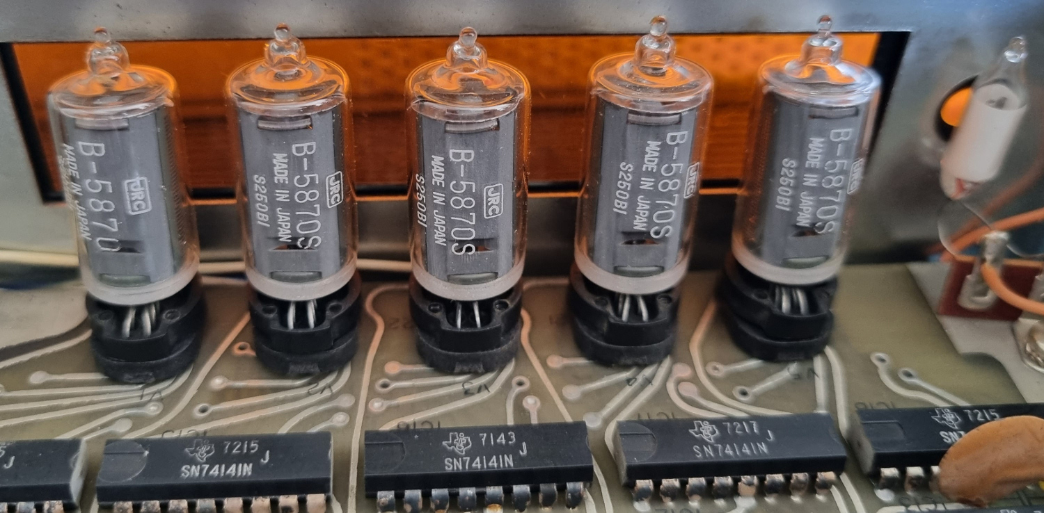
First I'd like to introduce the counter to you. Its main asset is, of course, its 5 digit nixie tube display. Frankly, if it had any other type of display it would have been a rather unappealing instrument. The display consists of five B-5870S nixie tubes, made by JRC. A small neon bulb is used as overflow indicator.
The counter has only two actual ranges.
The low range can count from about 5Hz up to some 35MHz and the high range counts from 30MHz up to 200MHz.
These ranges can be selected by a rather amateuristic looking toggle switch.
It's just like it has been added afterwards.
On the low range you can select between high or low impedance mode with the LOW/HIGH toggle switch.
The low impedance mode simply adds a 50Ω resistor in parallel to the input.
The high frequency range always has a 50Ω input impedance.
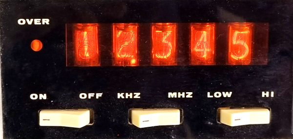 MHz mode shows 5 most significant digits
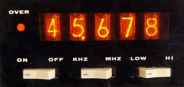 kHz mode shows 5 least significant digits
At first glance the kHz/MHz toggle switch may also look like a range switch too.
This is not the case though, it simply allows you to select which part of the frequency you want to see.
For frequencies up to 100kHz you best keep the switch in the kHz position.
The counter simply doesn't need more than 5 digits to display the entire number.
When you apply a higher frequency to the kHz mode it will still show the lower 5 digits of the frequency.
At the same time the OVER indicator will start flashing, indicating that there are more than 5 digits.
You can see those other digits by selecting the MHz mode, which basically divides the input frequency by 1000.
This then shows the remaining most significant digits.
The decimal point remains at the same position in either display mode.
In fact the counter changes its gate time from 1s for the kHz mode to 1ms for the MHz mode.
The OVER indicator is a bit primitive.
Usually a frequency counter does its counting in the background.
Once the gate time is over, the total count is copied to a latch, which holds that value to be shown on the display while a new measurement is started in the background again.
You would expect the OVER indicator to belong to the latched count value.
On this counter the OVER indicator will only light up for the current measurement which is being made in the background.
On top of that the OVER indicator flashes irregurlarly and is not always consistent.
E.g. when you apply a frequency of 99.999kHz, it does not light up, which is what you'd expect.
Increasing the frequency by 1Hz to 100.000Hz shows 5 zeroes, but the OVER indicator remains dark.
This could have been solved by adding two flip-flops (1 IC).
One flip-flop is set on overflow, the other one is used as a latch.
It simply shows that TTL logic chips were still rather expensive in the seventies.
Also note that this counter can only count frequencies. It cannot count period times, which would have allowed you to measure lower frequencies with a much higher resolution.
Thus far I've explained the features of the YC-355D.
One rather interesting features remains to get some attention.
The instrument can be powered by AC mains, or by DC 12V.
Why is this something special then?
Many electronic devices can be powered by AC mains or DC low voltages.
On this instrument this is note worthy because it is a nixie counter.
Nixie tubes require a high voltage, much higher than what a typical battery can supply.
On this counter they've solved this by reverse driving the mains transformer when it is powered by DC.
A clever solution but it is very unlikely that I'm ever going to power it from a DC source.
Does It Work?
The Original Power Input
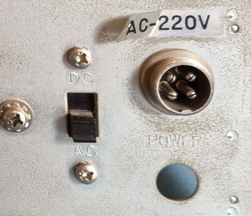 One input for AC or DC power
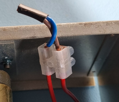 But this is what I had to work with
And there it was.
There was no proper mains socket, just a keystone with two short pieces of wire sticking out of it.
Apparently that's where I had to connect the mains power to.
Uhmm, let's not do that just yet, let me investigate the thing a bit further first.
It appears that the device can be powered by mains and by 12V DC.
Both have to be applied to the same small metal socket.
This may be a good idea for 100V mains in Japan, but I find it a bit scary to use a small metal plug for 230V here in Europe.
Anyway the plug itself was not included, so I couldn't use it, even if I wanted to.
If I can get this thing back to life, I'm definitely going to change the mains connection.
The PCB
 The inside of the YC-355D after restoration
All electronic components are mounted on a double sided PCB without a solder mask.
The holes are poorly plated, therefore all top layer connections are also soldered.
Luckily they've kept the number of top layer connections to a minimum.
Later I discovered that the traces of the PCB were rather fragile.
And on top of that all passive component leads were bend 90 degrees before soldering.
I hate that, it makes it that much more difficult to get them out without damaging the traces.
The high frequency prescaler is placed on a small separate PCB, as if it was an afterthought.
The simple toggle switch to select the high frequency range also looks as if an amateur has made an extension to the counter.
As for the manufacturing date, the youngest original IC that I could find had the date code 7237.
This means that the device probably dates back from late 1972, early 1973.
I must have been about 13 years old at the time.
The Oscillator Is A Great Mess
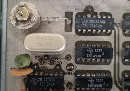 This trimmer cap doesn't look original
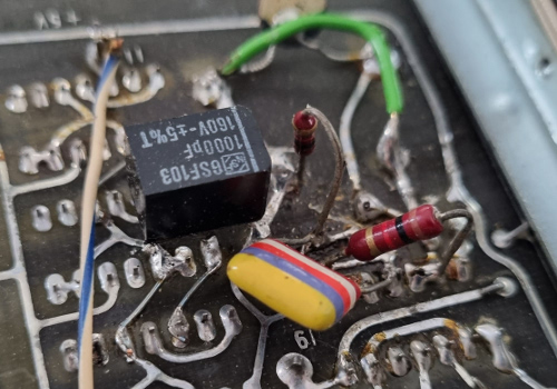 What a mess
Apparrently one or more of its previous owners have worked a lot on this little counter.
I already mentioned the mains connection, which will have to be fixed to make the device safe again.
Some of the ICs were not original.
All of the original ICs are from Texas Instruments, so it was quite easy to pinpoint the newcomers.
And the circuit around the oscillator has been worked on quite considerably.
Most of the passive components have been moved to the bottom side for a reason which is unknown to me.
Remarkably none of these components had their original value.
Supply Problems
Carefully I powered the logic circuit with 9V from a lab power supply to see what would happen.
The circuit drew little over 1A, which is acceptable for two dozen TTL ICs.
Oh no, the 5V rail is more than 7V, that can't be right.
I quickly tried to adjust the voltage back to 5V.
Mind you, I tried and failed.
The potmeter fell apart at the first touch.
Without proper feedback the power supply was stuck at it's maximum output voltage.
The only wise thing to do in this case is to remove the power and hope that no magic smoke has escaped from any of the parts.
I know I have not seen any magic smoke escape, but who knows what has happened to it before I powered it on.
It is not very likely that this fault was introduced just now.
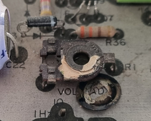 Falling apart
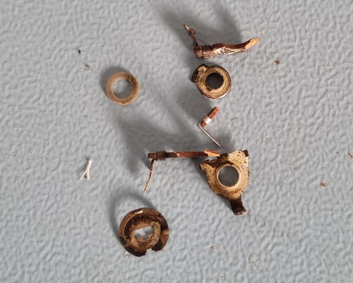 Potmeter remains
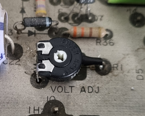 That's better
After replacing the potmeter I was able to adjust the voltage to the intended 5V again. That is problem number one fixed. How many more are there to follow?
The Oscillator Restored
Let's see whether the 1MHz oscillator works.
Much to my surprise it did.
Why did the previous owner rebuild the entire thing then?
Not only did he replace all the passive parts and placed them on the bottom side of the PCB, he also cut some PCB traces around the oscillator circuit.
But somehow the electrical connections remained the same.
Although the oscillator worked, it was impossible to calibrate it.
The frequency was and remained 999897Hz.
I carefully restored the entire oscillator circuit back to its original state. Well, I almost did, as I don't have a 400pF trimmer capacitor. For the time being a fixed 330pF capacitor should do the trick. All cut traces have been fixed as well. The entire circuit corresponds to the circuit diagram again.
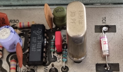 All components back where they belong
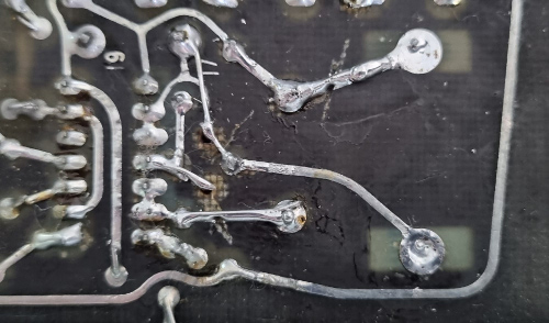 All traces fixed, as good as possible
The Oscillator Works Again
And the good news is that the oscillator still works.
Is everything OK now?
No, not quite.
Remember that I don't have a 400pF variable capacitor with which the oscillator should be tuned to exactly 1.000 MHz.
It appears that the oscillator cannot be tuned at all, eventhough everything is back to its original design.
The frequency was stuck at 999.897MHz and there was no way I could change that.
When this capacitor is below 40pF the oscillator appears to be very unstable.
With no capacitance at all the frequency is about 1.6MHz, which rapidly changes towards 1MHz.
And as soon as the capacitor hits some 40pF the frequency is 999.897MHz, even when I change the capacitor to 680pF.
For now I've settled for a fixed capacitor of 330pF.
I've decided I find this frequency good enough for this machine.
In case I need something more accurate I have alternative instruments available.
This machine is in my collection just because it has nixie tubes.
The fact that the oscillator is a bit low means that the frequency readings will be a bit high, who cares.
In the future I may add an external reference input to the instrument, which can be connected to a distributed GPS disciplined oscillator for the best possible accuracy.
No Risk, No Gain
OK, with the power supply and the oscillator working it is now time to take some more risks. So far the nixies remained dark because I haven't applied the high voltage yet. Let's power the machine up completely now and see what happens.
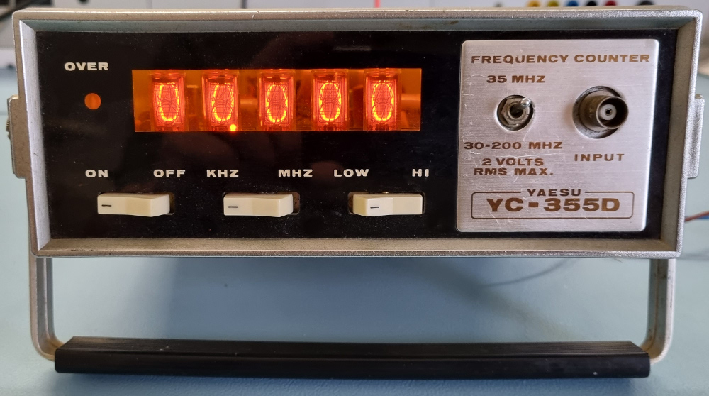 Wonderful, the nixies work, just like the seller has promised.
But does it work?
Input And Memory Problems
To test it I applied a signal with a frequency of 50Hz at 1Vpp to the input and you would expect the display to show 50 or something very close to that.
 Not even close to 50Hz
Alas, there were a few things not quite right. The indicated frequency was jumping up and down between some 450 and 520, or there about. And the counter was visibly counting for one second, after which it froze for another second to allow me to read the frequency. Older frequency counters didn't have an intermediate result latch, also called a memory. But this one should have a latch, at least that's what ICs 9 until 13 are there for.
 1kHz looks better
 So does 10kHz
 But 1MHz looks a bit blurry
Then I tried 1kHz.
Hello, this one showed up almost spot on.
10kHz was next, also spot on.
What about 100kHz then?
I had to select the MHz mode for that, but 100kHz was spot on too.
However this time I saw the counter counting, but there was no freeze time.
I could make out the final result because that was brighter than the counting.
This is because the gate time is just 1ms, followed by 999ms of idle time.
Anyway, 1MHz and 10MHz were OK too, apart from the strange visible counting behaviour.
Restoring The Memory
At some point in time IC1 and IC2 were replaced by LS versions, for whatever reason.
To start with, I decided to replace them for the original Texas Instruments 7404 and 7400 types respectively.
Somehow that did fix the weird memory behaviour on both the kHz and the MHz modes.
Now on both modes the counter counted in the background and then copied the result to the latch before starting the next counting cycle.
Apparently there was something wrong with the timing of the signals when LS family members were used.
The only problem that remained was that frequencies below some 700Hz were way out of tolerance.
Other Newcomers
Judging by the date codes, brand names and soldering residue I noticed some of the other ICs were replaced too.
IC 6, the middle digit counter was replaced by a different brand (looks like FLJ or something).
I left that one in as the counter does its job properly.
And IC19, the oscillator 7400 was replaced by another Texas Instruments IC.
Its date code of 7407 made it far too young to be original.
I left this one in too for several reasons.
At least it's of the right family and the same brand name.
The oscillator works and I doubt changing it will fix my inability to tune the oscillator to the exact 1MHz.
And I didn't dare to risk more soldering on the already badly damaged PCB traces around the oscillator.
Silly Input Amplifier
I guess we're almost there. One mystery remains to be solved and that is the strange behaviour of the counter at lower frequencies. It appears that the problem occurs at frequencies below some 200Hz, with amplitudes above 400mV, or there about. In those situations the counter reads way more than what is applied and the counted frequency is very unstable.
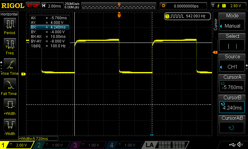
Let's start by measuring the signal on the digital input of the counter (pin 12 of IC1). Do you notice something strange in the signal above? The signal looks clean enough. However the frequency counter in the top right corner tells us that the frequency is 542Hz, while the frequency between the cursors is just 100Hz. That doesn't match.
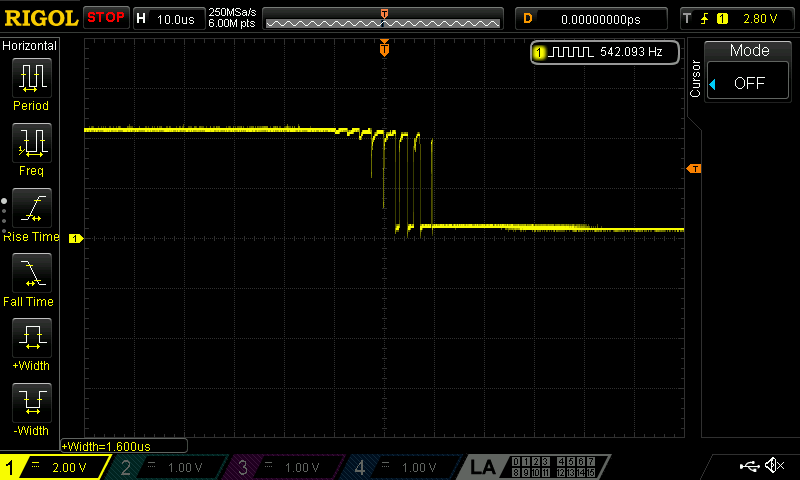
Let's take our magnifying glass and zoom in on the apparently clean edges. The rising edge is clean. But the same can't be said about the falling edge though! It appears to be oscillating there. At least that explains why the counter shows such erratic values.

Let's focus our attention around Q3, the last stage of the 3 transistor input amplifier.
Its input (blue line) looks clean.
However its output oscillates during the rising edge.
What can possibly be the cause of that?
The coupling capacitors perhaps?
One of the capacitor cans was easily squashed when I was trying to take it out with a pair of pliers.
It was just as if it was completely empty.
But alas, replacing the caps didn't solve the problem.
Q3 itself may be faulty.
Let's see if I've got one.
Yes, according to my component database I do have some 2SC1047 transistors.
All of my Japanese NPN transistor stock is in one box.
I was much surprised to find the bag I needed on top of the pile in that box.
But sadly, replacing the transistor with its original brother or sister didn't solve the problem either.
After some experimenting I settled on a fix which only consists of 2 small pieces of wire. Each wire on its own didn't solve the problem completely, but joined forces did solve it after all.
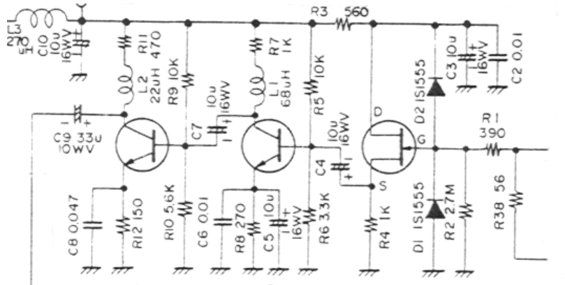
Notice that the input amplifier is basically a source follower input stage followed by a 2 stage audio amplifier.
Nothing special, no Schmitt-trigger attempts, no filtering, no gain control, nothing.
We're not trying to amplify audio though, we want to create a neat square wave.
We need some serious clipping to occur!
Anyway, after shorting the emitter of Q3 to ground and shorting the inductor L2 on its collector the problem was gone.
I don't promise that the circuit will ever oscillate again on particular frequency/amplitude combinations.
But at least no oscillation took place any more on the values that I did check.
Powering The Prescaler
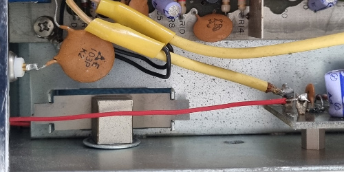 It's a long way home
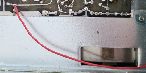 And back
I have already mentioned the amateuristic way in which the high frequency prescaler was added.
Not only does the toggle switch on the front panel look out of place, also take look at the detour the power wire to the module has to make, all around the hinge mechanism.
One little hole, drilled through the PCB, is all it takes make a more direct connection to the +5V line.
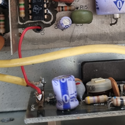 Doesn't this look better?
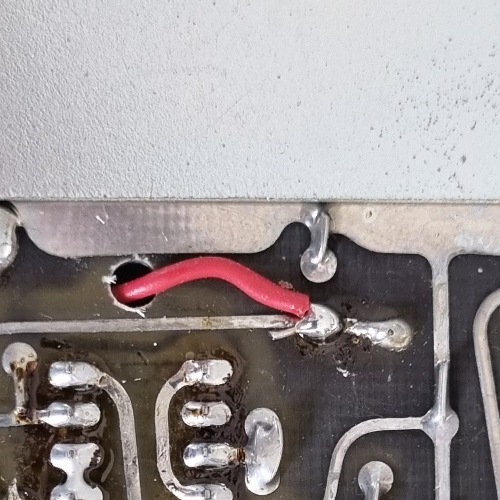 And this?
I also noticed that the supply voltage to both input amplifiers dropped about 0.5V due to the load of the prescaler, in series with L3. Disconnecting the prescaler did not improve the functionality of the input amplifier though, so I left the connection as it originally was.
Making It Safe For 230V Mains
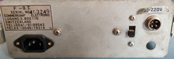 Just like it's always been this way
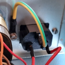 Inside view
I think I can call the restoration a success.
Now its time to make it a safe instrument again.
On the back plane I found a space which appeared to have the exact size for an IEC C14 receptacle.
All that needs to be done is drill some holes and use some elbow grease to file the main hole to have the exact size.
This took most part of an hour to achieve, which was well worth the effort.
It simply looks as if it came right from the factory this way.
B.T.W. I did remove the mains wires from the original connector.
Otherwise they would have exposed the 230V on an easily accessible surface.
The original power connector can still be used to DC power the instrument, although I doubt I will ever do that. I have no idea what the hole below the power connector is doing there, but that can be used as input for an external reference signal in the future.
No Capacitors Replaced?
No, the original caps were all OK.
Some, so called electronic engineers, pride themselves to be able to replace all the capacitors and then claim to have fixed a device.
I rarely have to replace capacitors.
I don't say it never happens, I'm only saying it is not always necessary and it hardly ever is the solution to the problem of a device.
The End
Or is it? I may be tempted to redesign the circuit behind the OVER indicator by adding two latches. And I may add the ability to apply an external reference signal to the counter to make it more accurate.
I don't think I'm going to improve the pittyful input amplifier or crystal oscillator though. The counter is beautiful as it is, with its gorgeous nixie tubes. And that is its entire purpose in life from now on.
