Philips PE-1542 Tripple DC Power Supply

When I bought this device, about half a year ago at the time of this writing, it was not functioning properly. The voltage settings were all over the place, at least on 2 of the 3 outputs. The minimum voltage was way too high, and the voltage was sometimes dancing up and down without any load. Clearly the device was in need of some love and attention. I had other things to do then, so I was not able to give it the much needed attention. Fortunately things are settling down a bit, allowing me to spend more time on my favourite hobby again.
What I Like About This Instrument
First of all, the looks. With its 3 analog panel meters it looks quite impressive, especially for such a compact unit.
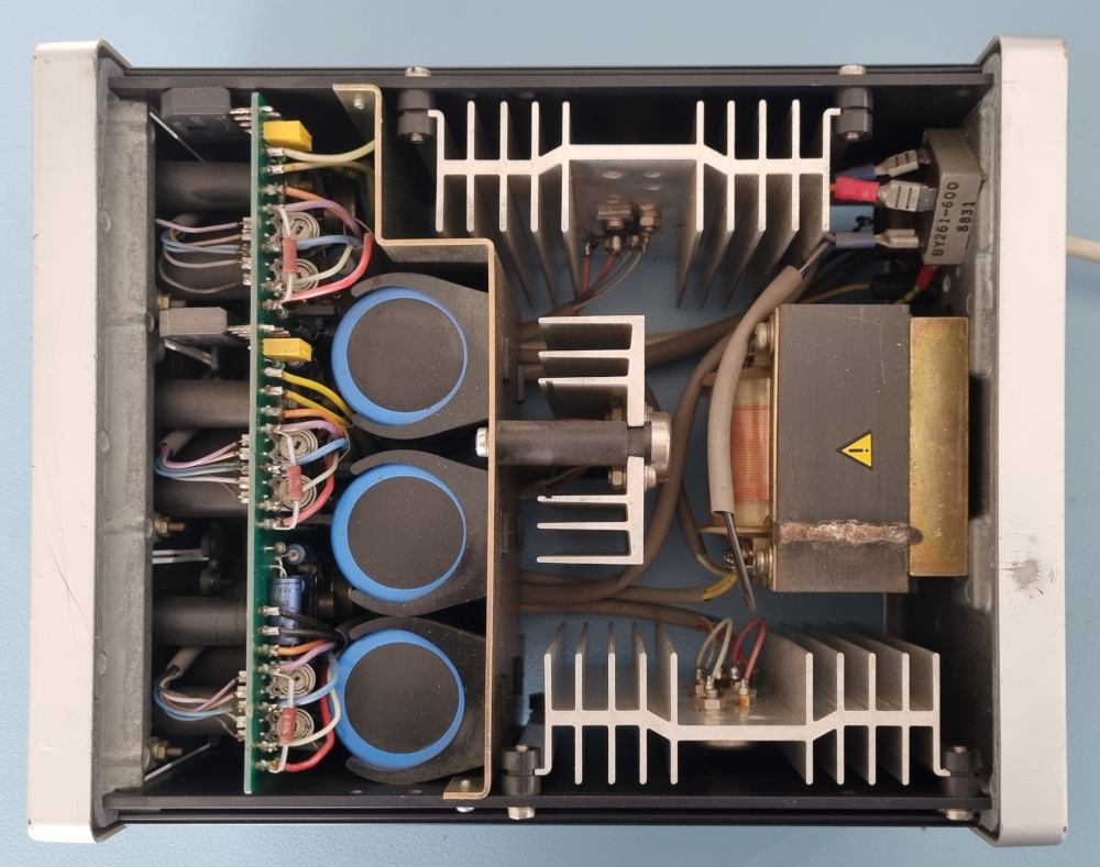 Not much space wasted inside
It has 3 fully independent outputs, each capable of supplying 20 Watts.
This is more than adequate for most applications.
Two of the outputs can be adjusted from 0V to 20V and can deliver 1A each.
The third output can be adjusted from 0V to 7V and can deliver 3A.
An ideal supply for mixed analog and digital circuits.
All outputs are totally independent from each other.
This allows you to connect outputs in series or in parallel to increase the maximum power delivery.
Or you can use the two 20V outputs as a symmetric output pair.
Shortcomings
Unfortunately the 3 panel meters can not show the voltage and current of an output simultaneously. But what do you expect for such a compact unit? Three slide switches allow you to select between voltage or current to be shown on each individual analog panel meter.
Sadly the instrument also doesn't show whether the supplies are in Constant Voltage or Constant Current mode. However that shouldn't be an issue for 95% of all use cases anyway.
And it does not feature output on/off control, which is quite common for old analog power supplies. It would have been nice to have output on/off control, especially if it could control all 3 outputs simultaneously. Usually devices with symmetric power requirements are quite sensitive to switching behaviour of the power source.
And, as was very common for most multi output power supplies back in the days, all outputs are truly independent from each other. There is no way to make one output to track the other to simplify adjusting symmetric outputs. Features like these were only introduced when lab power supplies were digitised.
And finally, the power cord is not detachable.
This is quite a nuisance when you quickly want to take the supply away from the workbench.
Then you'll have to wiggle the power cord free from the tangle web behind the workbench.
With a little will power and some elbow grease this can be fixed in about half an hour.
I think an ICE receptacle can fit in the corner where the power cord enters the device.
Despite these shortcomings Ilm very happy with this little unit, even though I would have preferred the older blue style, above the younger brown style of my instrument. Beggars can't be choosers.
Getting Inside
Opening the device was not at first very obvious. There's not a single screw in sight. Fortunately the user manual gave the golden tip. You have to shift the front and rear rims ever so slightly to allow the top, and alternatively the bottom plates to come off.

Be careful not to break the rims though. After all the plastic is already rather old.
Finding The Problems
Only one of the three outputs was working correctly when I bought the unit.
The other two had arbitrary minimum voltages which were way above 0 Volts.
I can remember that one of the 20V outputs wouldn't go below 6V.
Later that same output wouldn't go below 13V.
The maximum output voltage was no problem on any of the three outputs.
And I noticed that the current meter from one of the outputs was dancing up and down, while the output current was a nice stable 1A.
From the very start I suspected the trimmer potmeters to be the cause of these problems.
My only problem was that I did not have a proper service manual.
It is very easy to find several versions of the user manual online, but a service manual was nowhere to be found.
I found one download which promised me a service manual, unfortunately it was a user manual, again.
 The circuit diagram of one of its channels
Luckily the user manual does have a circuit diagram, but it was rather difficult to match the diagram with the trimmer pots.
There's no silkscreen on the PCB and I was very reluctant to dismantle the device completely.
The main PCB is mounted vertically behind the front panel.
The fact that the unit is very compact and reasonably well built doesn't necessarily mean that it is easy to service the thing.
Taking it apart means I had to remove the decal from the front panel, remove the screws behind it and remove all output connectors.
On top of that I expect all cables to be too short to move the PCB into a comfortable position.
On the positive side, all trimmer pots are located either on the top or bottom edges of the PCB, that's nice.
Each output has 6 trimmer pots, but which one is which?
The circuit diagram alone wasn't very helpful either, because there were no component values in it.
Fortunately the user manual also featured a BOM list.
However the values in the BOM list don't always match with the values found inside the device.
With some annotations in the circuit diagram I could finally figure out what the purpose of each of the potmeters was.
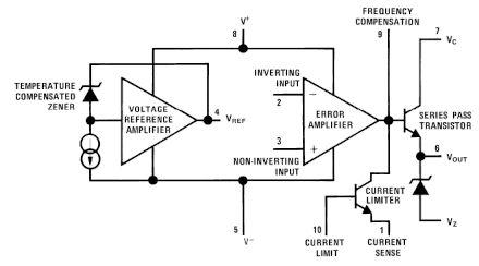 Basically each of the 3 output channels has exactly the same circuit diagram.
Only the values of some components for the 7V output are different from the other 2 outputs, as might be expected.
The circuit is based around the LM723, a very common multi purpose linear voltage regulator from the seventies.
It generates a temperature compensated reference voltage of 7.15V. And it has a separate error amplifier which can drive the series transistor.
One commonly recognised drawback of this device was that it was not easily possible to create a variable output voltage which went all the way down to 0V.
A negative bias was required for that, something which is also present in this circuit.
Please note that a lot of trimmer potmeters are used to tune the circuit to the desired specifications in this design.
Six in total, per channel.
I'll explain what each and every one of them does later on.
Also note that in this power supply the round metal can package is used.
That should make it easier on you if you try to match the pin numbers with the functions from the datasheet, should you ever need to do that.
Eventually I figured out that indeed the semi variable resistors, also known as trimmer potmeters, were to blame.
At first glance they appear to be good quality ceramic based components, not those cardboard based rubbish.
A common cause with old potmeters is that they tend to get dirty and therefore unstable.
My guess with these potmeters however is that over time they have started to develop mechanical cracks, which causes a dramatic increase of the resistance of the wiper track.
I wanted to know absolutely sure that the potmeters were to blame so I used several different approaches to test them (measuring voltages, testing continuity, measuring resistance values).
All these tests pointed towards the same conclusion:
The potmeters were not to be trusted, especially the ones with values below 1kΩ.
For this diagnosis it was very helpful that I had one working output, which allowed me to compare the faulty and good outputs.
So now I know that none of the trimmer pots can be trusted, not even the ones which still appear to be good.
I'm going to change them all.
Keep in mind that the lowest possible output voltage can rise several volts when the potmeter fails.
This can be disastrous when this happens while powering an expensive and sensitive circuit.
Now my only hope is that I can replace them without having to remove the PCB.
Replacing The Pots
That's easier said than done.
Looking at the schematics and the BOM I found pots with values of up to 22k.
However in reality I found some of the pots to be very different from what I found in the diagrams.
My best bet is to stick by the values which are in the device, or at least as close to them as possible.
A semi variable resistor can be wired in two different ways.
One way is as a real potentiometer, where all three connections are used.
The centre tap being the wiper.
And the other way is as a variable resistor, where one of the ends is left open, or connected to the wiper.
It turns out that 4 of the 6 pots per output were used as variable resistors, and 2 were used as potmeters.
If you try to find replacements for a variable resistor the exact value isn't that critical.
A 150Ω pot can be replaced by a 250Ω pot for instance.
The disadvantage is that you will have less resolution, making it possibly harder to find the sweet spot while adjusting it.
In this example you might even get away with a 100Ω pot, if you're lucky enough that you don't have to adjust it past 100Ω.
The advantage of this is that you will have more resolution, making it easier to hit the sweet spot, if you can get there.
Potentiometers on the other hand are a different story.
Especially if they are part of a voltage divider in the circuit.
For those you preferably want to use exact replacement values.
On top of that I preferably want standing potmeters, instead of horizontal ones, as I'm going to replace the existing standing ones.
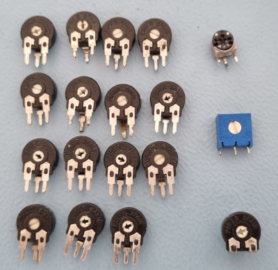 Replacement potentiometers in no particular order
I did manage to find suitable replacements for almost all potmeters, without having to buy any new ones. Most of them look identical, only a few look a bit different. And now we're going to start the difficult task of finding out which one is which.
All components for the 7V output are numbered in the 100 range, except for the front panel potmeters, switch, outputs and panel meter. The middle power supply has the component numbers in the 200 range, except from the front panel parts again. And the 20V output on the opposite side has components in the 300 range, except for the front panel components.
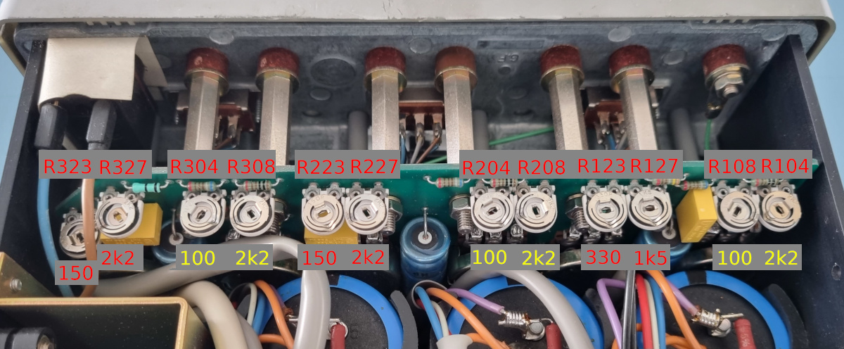 The yellow values are to be matched precisely
Along the bottom edge of the PCB you'll find most of the potmeters, as can be seen in the picture above. There are 4 potmeters for each output, numbered accordingly. The ones with their values in yellow need to be matched precisely because they are part of some resistor networks. The ones with their values in red are not that critical, because they are used as simple variable resistors. E.g. the 150Ω ones I have replaced by 250Ω, and the 330Ω is replaced by a 470Ω potmeter.
 The potmeters for the panel meters
Along the top edge of the PCB are 2 potmeters for each of the outputs. They control the adjustment of the panel meters, one for voltage, the other for current. Unfortunately they are bit harder to reach because of all the wiring which gets quite in the way.
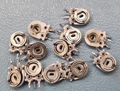 Scrap
Scrap
Fortunately the PCB is a good quality through-plated version, so I was not able to damage the PCB itself.
However, the downside of a through-plated PCB is that you can have difficulty opening the holes after removing the old component.
That's why it took me a bit longer than anticipated to replace all the potmeters of the bottom edge.
I have added some fresh solder to each of the pins and then heated all three pins per potmeter simultaneously, which allowed me to carefully wiggle the old potmeter out of the PCB.
After that I only had to suck the solder from the holes, place the new potmeter and solder it back into place.
Easier said than done under such awkward angles, especially R323 which is recessed a bit, with some wires running over it.
During this process one of the pins of a potmeter broke off.
Oddly enough it was R223, the only one of its kind which was still working good before I started swapping the potmeters.
Then I turned my attention to the top edge of the PCB, where the panel meter adjustment potentiometers are. There are a lot of wires running up and down the PCB there, on both sides. I did some extra testing and noticed that these potmeters are all still good. So I'll leave them as is for now. The low value potmeters tend to fail first. And these are for the current scales, which are most likely hardly ever used anyway.
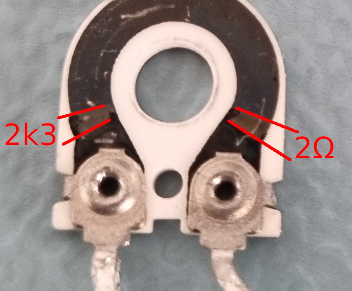 No signs of any cracks, but this can't be right for a 100Ω potmeter
Judging by the measurements I've made on one of the potmeters I think it's safe to say that all was not done in vain.
After the replacement of the potmeters on the bottom edge all 3 outputs worked flawlessly again.
(I haven't told you yet that I immediately calibrated each individual potmeter directly after replacement).
After that I have cleaned the front panel potmeters and slide switches with some squirts of deoxid.
And that also solved the dancing of one of the current meters while delivering a constant current.
Calibration
Now that everything is working again we can start the calibration. Normally this would possibly not have been necessary. But since we've changed almost all variable resistors in the box, none of them will likely be in the best possible position.
For starters the calibration is not super complicated.
All you need is a voltmeter that you trust, a dummy load and also an Amperemeter which you trust.
So basically you could get away with a decent multimeter and a 25W resistor of some 2Ω.
No, don't get tempted to use your 100 W loudspeaker as a DC dummy load!
I've used my Tenma electronic dummy load as an accurate voltmeter, amperemeter and as a dummy load.
Then consider the fact that you are basically calibrating 3 very similar power supplies.
So basically you perform the same trick three times in a row.
I'm going to explain the calibration for just one of the outputs.
This can then be repeated for all 3 outputs.
 All the pots on this side replaced
Important note, make sure your brand new potmeters are set somewhere in the middle. I myself failed to do that for the 7V output. Two of the current limiting potmeters were set all the way to the left. It startled me that the supply refused to output any voltage after the potmeter swap. I hadn't heard a loud bang though, so things could not be terribly wrong, but still, I had no power. Great was my relief when I discovered that the settings of current limiting potmeters were to blame.
Adjusting the Voltage offset
The purpose of this setting is to allow the power supply to regulate all the way back to 0V, without overdoing it. If this setting is wrong you will either find that you can not set the output to 0V, or you will notice that the Voltage knob is dead for about half the scale. You want the voltage to rise as soon as you turn the Voltage knob away from its counterclockwise position.
Set the Voltage knob to the counterclockwise position (turned all the way to the left) and the Current knob to the clockwise position (turned all the way to the right). Measure the voltage on the output, without any load. Now adjust R123 (R223, R323) carefully so that the output voltage just hits 0V. If the output voltage starts to rise, you're too far. If the output was already 0V when you started, make it rise a little first and then return to 0V so you'll know that you've hit the sweet spot.
You can check the adjustment by slowly turning the Voltage knob clockwise. The voltage should start rising immediately. If nothing happens at first, your calibration has not been successful.
Adjusting the maximum output Voltage
The purpose of this setting is to set the maximum output Voltage to its specified value. You want the 20V outputs to at least reach 20V, and the 7V output to reach at least 7V. Anything lower than that is not good. I've allowed for some 5% overshoot, to make sure the supplies can definitely supply the maximum voltage. A little overshoot is fine, but don't overdo it.
I've inherited a power supply kit once, which was built by the person who gave it to me. He had set the output voltage as high as he could set it. "Free power", must have been his reasoning. But keep in mind that the power supply needs some buffer to compensate for the voltage drops on heavy loads, and that the input voltage from the mains may vary by ± 10% too. 10% less on the input, automatically means a 10% lower absolute maximum on the output too.
Anyway, first rotate the Voltage and Current knobs clockwise.
Measure the output voltage without any load.
Now adjust the output voltage to its maximum value +5% with the potmeter R127 (R227, R327).
After this you can check whether the Voltage offset is still OK by briefly returning to the previous step.
You're done when the output voltage is nicely 0V when the Voltage knob is turned counterclockwise and the maximum voltage is the maximum voltage for that channel +5%.
Please note that the panel meters are not calibrated yet. So you'll have to check the voltages using your multimeter.
Adjusting the minimum output Current
The purpose of this adjustment is again to set the scale right, for the Current knob this time. The sweet spot is when the output current is 0A when the Current knob is rotated counterclockwise, and starts rising as soon as you start rotating that knob slightly clockwise.
Use a dummy load (a resistor of 2Ω / 25W) as a load during this adjustment. If you don't have one I think you can also get away by simply shorting the output with your Ampere meter. Make sure you set the range of your Ampere meter correctly before you start. The 7V output can deliver in excess of 3A if it is not properly calibrated.
Rotate the Voltage knob clockwise and your Current knob counterclockwise. Then use R108 (R208, R308) to find the sweet spot where your Ampere meter just reads 0A. When it starts to rise, you're too far. When it was 0A when you started, make it rise a bit first and then return to 0A.
If everything is set OK, the output current will be 0A with the Current knob rotated counterclockwise, and it should start rising as soon as you rotate it slightly clockwise.
Adjusting the maximum output Current
The purpose of this adjustment should be clear by now I guess. Rotate both the Voltage and Current knobs clockwise. Connect the dummy load (or use your Ampere meter to create a short circuit to the output). Adjust R104 (R204, R304) to make your Ampere meter indicate the maximum output current of that channel +5% again. So for the 20V channels, set the current to 1.05A. And for the 7V channel set the output current to 3.15A.
Once you've done that you can go back to the previous step and check whether you're still satisfied with the Current offset. You may have to go back and forth between this step and the previous step a few times to make it perfect.
Adjusting the Voltage panel meter
Before you begin, set the output voltage to 0V. You should be able to do that now. Move the slide switch on the front panel to V. And then adjust the mechanical screw, just below the panel meter to make indicate exactly 0V.
Do not connect any load to the output. Set the Voltage knob so your multimeter reads exactly the maximum output voltage (no +5% this time). Then adjust R139 (R239, R339) until your Voltage panel meter shows the Maximum voltage.
Adjusting the Current panel meter
You do not have to repeat the adjustment of the mechanical screw under the panel meter this time. But you'll have to move the slide switch to the I position.
Now load the output using your dummy load, or simply short the output with your Ampere meter. Adjust the Current knob until your Ampere meter reads exactly the maximum output current of the channel (no +5% this time). Then adjust R138 (R238, R338) until your panel meter shows the correct value.
That completes the calibration, for channel one. Repeat it for all three channels. Calibration is rather straightforward. It only looks complicated if you see it written down in steps.
Testing
Testing is simply done by going through all the calibration steps.
When all these steps can be completed successfully, we're almost home.
What else can there be wrong?
Capacitors of course.
Every self proclaimed electronics engineer at least has to know how to replace old capacitors.
But before I start ruining this perfectly restored unit, I'd rather check the capacitors first.
And that can simply be done by just about any old (or new) oscilloscope.
I simply set the output to the maximum voltage and maximum current. And then I connect a dummy load to make the power supply output 20W, or just slightly more than that, after all 7 x 3 is 21 W. If the output does not oscillate, and does not show any signs of ripple, it will be safe to assume that the capacitors are still fine.
And indeed I saw no signs of any problems. The maximum ripple on any of the outputs was below 5 mV p-p at full load. I also measured the ripple on the filter capacitors. You do expect a ripple to be present there, that's what the filter caps are there for. On the 7V output this ripple was 1.5V p-p, while on the other two channels the ripple was 0.8V p-p.
But how do I decide if that is acceptable or not?
Simple, by measuring the power reserve.
The lowest voltage measured on the filter capacitor (with the oscilloscope of course) was 13V.
So for a 7V output that gives a 6V reserve, at full load.
That is more than good enough.
And the lowest voltage on the filter caps of the other two channels was 28V, which is 8V reserve.
Also more than enough.
Of course I also checked the capacitors on leaking fluid. Everything was spotless, as if the unit had never been used before.
So, sadly for you capacitor aficionados, I'm not going to replace any capacitors in this old thing, again.
The Final Steps
My little triplet is perfect again. At least it works perfectly again. But is it perfect? No, there's still one thing that annoys me. And that is its fixed power cord. I want to get rid of it. Let me see if there is enough room for an ICE receptacle.
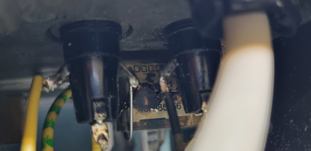 Hmmm. What's that down below there?
It looks all the world to be a dead RIFA X capacitor.
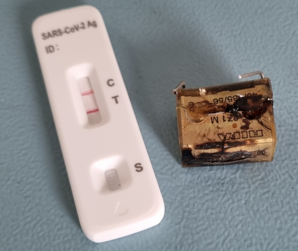 Yes, that is positively a sick puppy.
That must have been a fantastic smoke bomb when that thing started to fail! It must have scared the crap out of its previous owner, I'm sure. I know, I've been there, not so very long ago with my converted Elabo power supply.
I simply cut it from the circuit.
And I couldn't be bothered to put a new one back in again.
After all, it works perfectly without one.
And I do not intend to take the device through a renewed type approval anyway.
Damn, you capacitor fan boys were right again.
I did have a faulty capacitor.
But I refuse to admit it, I simply don't put a new one in.
Back to the matter at hand. Yes there is enough room for an ICE receptacle. It's just about half an hour of grinding and filing away. Bother it rains cats and dogs outside and I have to go to the toolshed to get my drill set up here. Anyway, about an hour later the unit had got rid of its tail and now sports a brand new, second hand ICE input.
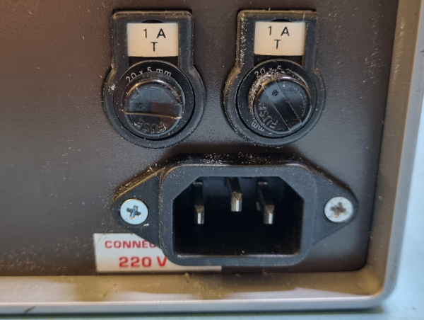 Perfect.
Do You Own A PE-1542 Too?
 If yes, I think now is the time to check whether you've got the same crappy potmeters as I did.
They might be an accident waiting to happen.
My recommendation is to replace at least the ones on the bottom edge of the PCB.
You'll never know when those things start to fail.
Knowing Murphy personally they probably start failing when you are powering your highly sensitive, very expensive, very rare and antique, vintage computer board......
