Fluke 8020A / 8022A
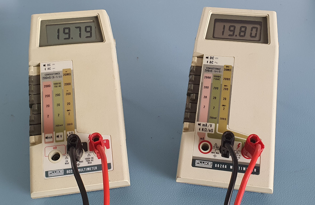
These are the real things.
Many brands have tried to copy them, but never really succeeded as far as I can tell.
I have very fond memories about these meters.
It was late 1979 when I started my internship at Fluke in my hometown Tilburg.
I guess these meters were at the peak of their popularity at that time, therefore I’ve seen lots of them.
At school we only had analog multimeters, which had to be treated very delicately.
It was absolutely forbidden to make the rotary switches of these meters to rattle by rotating them too fast.
In my last year I always took my Fluke 8020A with me to school.
I remember we even played football with it.
The Fluke meters were simply designed to cope with such abuse, much to the astonishment of the teachers.
On the analog meters it was absolutely not allowed to change the current range while measuring inductive loads.
The back EMF would destroy the range switch if you tried to do that.
On my Fluke I happily changed ranges as much as I liked, even overloading its range dramatically.
And it never ever failed.
The difference between the Fluke 8020A and the 8022A is its basic accuracy in the current ranges and the AC accuracy at higher frequencies was slightly worse for the 8022A.
In fact the only physical differences were that the 200mA and 2A current shunt resistors had different specs (indicated by a red or yellow dot of paint on the resistor’s body) and the RF trimming capacitor was not assembled in the 8022A.
The B versions of these meters came out after my internship.
It appears that on the B version they've managed to cram an HRC fuse holder into the battery compartment to make the meter a bit more safe to be used on high energy installations.
And a continuity function was added.
Production process
In the production hall two semi-automatic component placers were placed side by side.
Each placer had a revolving carousel with multiple compartments, containing all the components to be placed on the PCB.
Only one of those compartments was accessible at any given time.
A foot paddle would forward the carousel to the next component to be placed.
A fixture could hold the PCB panel, containing 2 PCBs.
A bundle of optical fibers was placed in an especially prepared PCB panel.
This caused some holes in the PCB panel to light up to indicate the location where the currently accessible components had to be placed.
All assembled PCBs were then placed on a wave solder machine.
Any grease and flux residue on the PCBs was cleaned off by submerging a basket full of PCBs into an open bath of freon.
Those were the days, before the invention of greenhouse gasses.
Then the PCBs were washed in an industrial dishwasher with demineralised water.
After drying the PCB panel was placed upside down into a jig.
An operator would then move a fast spinning router over the back side of the PCB to cut all wires short.
Sometimes a piece of cut wire would lie in a corner of the jig.
When the operator was not careful this caused the PCB to be raised a bit on one side, resulting in cut traces on the PCB.
Sometimes these cuts were only superficial.
Fluke’s high quality demands resulted in discarding such PCBs even when they were still fully operational.
They were thrown into a large box, waiting to be destroyed.
For some mysterious reason this box never overflowed.
Many of those PCBs were rescued from the box.
And the meter was then completed with rejected displays and housing parts to create an almost perfect meter for us, poor students.
I’ve donated plenty to my friends myself.
Almost an entire meter could be assembled from rejected parts.

Displays for instance were rejected when some segments had a different contrast when viewed under specific angles.
The bottom shell was often rejected because the operator of the pneumatic screw driver had poked a hole in the shield, which was an integral part of the bottom shell.
The top shell was sometimes rejected because the operator had forgotten to put a plastic collar around the screw posts.
This resulted in splitting of the screw post.
The battery door, the power switch knob, the screws and the strip underneath the range selector buttons were rarely ever rejected, so those usually were brand new.
Anyway, I still have two of those meters today.
They only needed new displays at some point, because the displays went completely black.
A very common issue, probably because the LCD technology was still at its infancy in 1979.
The displays for the 8024A were slightly different and were backwards compatible.
And to my knowledge they never suffered from the same problems as the displays for the 8020A and 8022A.
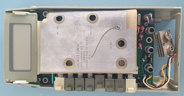
A climate chamber was placed in the cubicle where I was put to work. Every day a batch of brand new 8020A or 8022A meters were put into the climate chamber for 24 hours to see whether they would survive all kinds of weather conditions. I distinctly remember that at the end of the test some meters might still show 000, even when the battery was removed. That was caused by a faulty oscillator, which resulted in the LCD display being driven by a DC voltage instead of a 100Hz square wave. And that caused burn-in to the LCD.
Calibration
Calibration of these meters is very simple.
There are only 3 adjustments to be made.
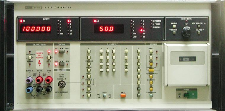
At Fluke they used a 5101B calibrator to supply all the voltages, currents and resistances.
A small data cassette held the program, which was walked through step by step to calibrate and verify all functions and ranges.
One minute the calibrator outputs a resistor value of 1000 Ohms, the next minute it outputs an accurate DC voltage of 1000V. Quite a remarkable machine.
You don’t need a machine like that to calibrate your 8020A though.
Just a reference voltmeter, a power supply and a function generator will do.

First you need to calibrate the DC ranges.
Apply a known DC voltage, which is close to the full scale of the meter (Fluke used 190.0mV).
Then adjust the DC cal potmeter.
After that the meter was checked on all DC volt ranges on both polarities.
Because the input divider was fixed and laser trimmed this never caused any rejects as far as I can remember.
The DC current ranges were also checked of course.
But no adjustments were needed or possible here either.
Then an AC voltage of 50 or 60Hz is applied, again close to the full scale value.
Fluke used 190.0mV again).
The AC cal potmeter is then adjusted.
After that all other voltage and current ranges were checked again.
And here I never saw any rejects either.
Finally, on the 8020A a voltage of 190.0mV at 10kHz was applied and the RF trimmer cap was adjusted.
That’s all there is to it.
All Ohms ranges were also tested.
However no adjustments were necessary or possible here.
Below I’ll explain a bit more how the Fluke 8020A measured resistances.
I have seen a certain batch of instruments fail on the Ohms range at some point.
This was quite exceptional, because the resistance measurements were always spot on.
It appeared that during the preparation for the assembly one of the component compartments was filled with a wrong type of capacitor.
The value was correct, but the type was wrong.
The correct type had purple markings, whereas the wrong type had black markings.
Remember that the Fluke 8020A is not a true RMS meter, which means that its AC accuracy is only valid for sinusoidal input voltages or currents.
A 50Hz Or 60Hz Crystal
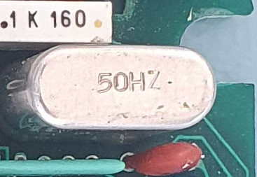 I’ve seen youtube videos where the vlogger was amazed about the low frequency of the crystals used in these meters.
To cut a long story short.
The frequency indicated on the crystal is not the actual frequency.
It indicates the mains frequency for the intended market.
It allows for a better common mode rejection by selecting the integration time to be an integer multiple of the mains AC period time.
For the 50Hz market the crystal has a frequency of 3.200MHz, resulting in a measurement rate of 2.5 readings per second.
For the 60Hz market the crystal has a frequency of 3.840MHz, resulting in a measurement rate of 3 readings per second.
Resistance And Siemens Functions
I want to elaborate a bit about the clever and at the time probably unique way of measuring resistances.
At the heart of the Fluke 8020A is a single chip dual slope A/D converter, which can also drive the display.
Most of its pins are used to drive the LCD display.
Four pins are dedicated for the 2 analog inputs.
The unknown voltage is applied to one of the inputs.
A known (calibrated) reference voltage is connected to the second input.
In principle the analog to digital converter measures the ratio between the unknown voltage and the reference voltage.
And since the reference voltage is a nice round 1.000V, the calculation is very simple.
Even for a chip which does not contain a microcontroller.
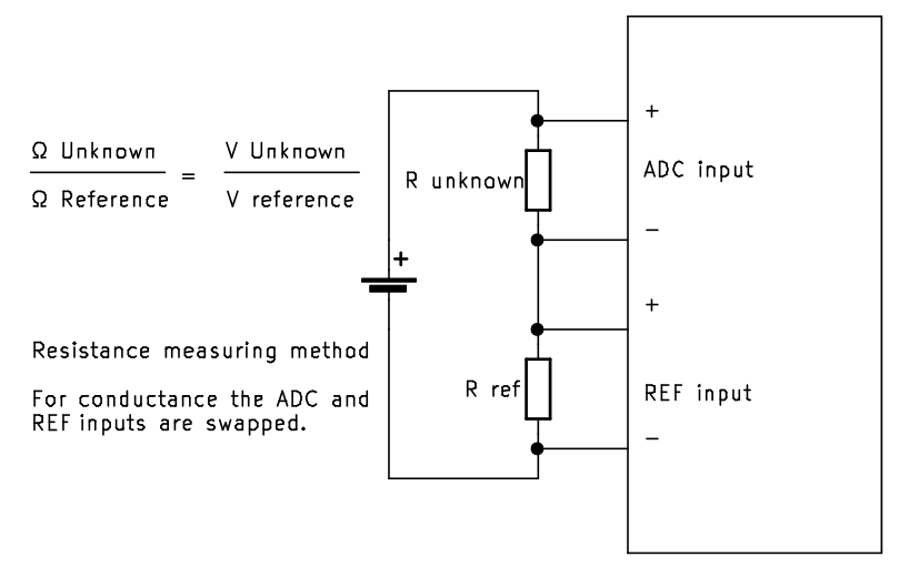
In the resistance function the voltage input divider is used as a reference resistor, the chosen value depending on the range.
This known resistor is placed in series with the unknown resistor.
A voltage is then applied to these two resistors.
The voltage across the unknown resistor is applied to one of the ADC inputs.
The voltage across the known resistor is applied to the other ADC input.
And again the meter displays the ratio between the two.
This way there are no adjustments to be made.
The known resistor is accurate and was laser trimmed.
And the applied voltage is not really relevant, because we only measure a ratio.
The Fluke 8020A uses two different drive voltages.
A low voltage for some ranges (200Ω, 20kΩ, 2MΩ).
And a slightly higher voltage for the other ranges (2kΩ, 200kΩ and 20MΩ).
The ranges with the lower voltages can be used to measure resistances in circuit, with reduced risk of diodes and transistors starting to conduct, ruining your measurement.
The other ranges, especially the 2kΩ range can also be used to test diodes.
The 2kΩ range can supply the highest diode forward current.
And now for a free treat.
If you press the top two grey knobs simultaneously in resistance mode the meter enters its 200nS (nano Siemens) range.
Pressing the top grey button and the 2k button simultaneously will enter the 2mS range.
Perhaps you already know that 1 Siemens is 1/Ω.
And that is exactly what Fluke did.
In the nano Siemens range the two inputs to the ADC are swapped.
For the 200nS range the reference resistor of 10MΩ is now connected to the unknown value input, and the unknown resistor is connected to the reference input.
With this 200nS range you can measure much higher resistances than in the maximum 20MΩ resistance range.
Please note that 0.1nS equals 10G Ω! Personally I do not see any benefit for using the 2mS range.
Protection And Safety
For the time this meter had excellent protection.
For instance the current ranges were protected by two beefy diodes, placed anti parallel across the shunt resistors.
That means that the voltage across the shunts and switches could never exceed the forward voltage of the diodes.
This not only protects the shunt resistors in case of an overload, it also protects the switch while measuring currents through an inductive load while switching ranges.
A 2A fuse simply protected against overload above the maximum current range.
The voltage ranges were protected by a set of varistors.
The instrument doesn’t even mind if you would put 1000V on the 200mV range.
The resistance function was protected by a PTC resistor, which dramatically increases in value when the current through it exceeds a certain safe threshold.
After an overload that resistor needs to cool down first, perhaps for a few minutes, in order to restore normal functionality after an overload.
In terms of safety, however, there was still something to be learned.
There was no HRC fuse on the current range for instance.
And no safeguards against internal explosions or arcing.
No shrouded banana plugs.
No finger guards on the probes.
And there was a DC power input jack, which could expose the dangerous common terminal voltage when used.
And as an extra side node, the safety of the entire system could be degraded by using a low quality power supply.
Remember that the common terminal is allowed to be taken 500V above earth level, and so will be the voltage on the power supply!
Anyway, in the past multimeter operators were considered to be a lot smarter than today.
Or perhaps they were expendable.
Aging
Apart from the display quality of the earlier units, these meters age very well. Because of their calibration simplicity there is not much which can go wrong with them.
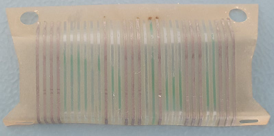
However after 40+ years the quality of the plastic is no longer what it used to be.
So I strongly advise you not to open the meter unless it is absolutely necessary.
The display bracket screw holes can be cracked or are likely to be very brittle.
And the display ribbon cable appears to fall apart when you physically handle it.
Without any effort you can rub all the traces off of this ribbon cable.
And replacements are virtually impossible to come by.
All higher capacitor values are tantalums.
I have not seen any of them fail so far.
So it is very unlikely that you need to open your meter to recap it.


