SAA1062 LCD Driver
As you can see elsewhere on my site I own a nice little Philips frequency counter PM6668.
This little counter contains a seven digit LCD display which is controlled by three SAA1062 LCD controllers.
Each controller can drive up to 20 LCD segments.
Remember that in the old days LCD segments were not multiplexed, which means that each segment required its own segment driver.
This page describes how this SAA1062 works and how you can control it.
However this page is by no means intended to be a replacement for the data sheet because important information is missing, for instance timing details.
Please don't ask me for the missing details, I didn't include the missing details simply because I don't have them.
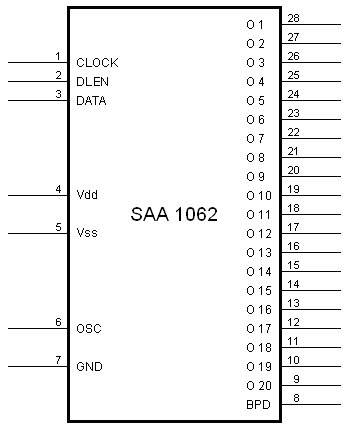
Pin Description

| Pin number | Pin name | Description |
| 1 | CLOCK | Positive clock pulse |
| 2 | DLEN | Positive Data Latch ENable |
| 3 | DATA | Data shift input (change during CLOCK=0) |
| 4 | Vdd | +5 V power supply |
| 5 | Vss | Power ground |
| 6 | OSC | Oscillator input |
| 7 | GND | Oscillator ground |
| 8 | BPD | Back Plane Driver |
| 28 to 9 | O1 to O20 | Segment drivers |
A capacitor of 22n is connected between the OSC input and the GND pin which will generate a typical segment clock of approximately 60 Hz.
In this mode the SAA1062 operates as the master device.
However, if the OSC pin is shorted to GND the SAA1062 operates as a slave device, in which case the BPD pin becomes an input.
There is always only one master SAA1062 with as many slaves as required.
Simply tying all BPD pins of all devices together will ensure that all devices are in sync with each other.
The outputs O1 to O20 directly drive the LCD segments, whereas the BPD pin is connected to the LCD's back plane terminal.
LCD Operation
Old fashioned, non-multiplexed, LCD displays are rather simple to interface.
Simply apply an electric field between the segments you want to show and the back plane is all you need to do to make it work.
Although.....
If you apply a static electric field like that for a longer period of time you might as well remove the electric field after 30 minutes because the segments will remain visible for ever after.
This is because the segments will "burn in" if you apply a DC voltage over a longer period of time between the segment and the back plane.
This "burn in" is easily avoided by constantly switching the polarity of the electric field.
You usually get the best possible results when the switching frequency is around 50 or 60 Hz.
Take particularly great care in selecting the clock source because the duty cycle should be exactly 50% in order to avoid any remaining DC component.

Thus the polarity is switched at a rate of approximately 50Hz.
This means that at one time the voltage between a visible segment and the back plane is +5 V, and during the next half period the voltage is -5 V.
Don't be tempted to simply switch the segment voltage on/off, because that still leaves an average DC component between the segment and back plane of 2.5 V.
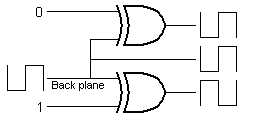
A segment is not visible if the voltage on the segment is in sync with the voltage on the back plane, thus when both signals are in phase with each other.
 The simplest way to drive an LCD segment is by using an Exclusive OR gate.
One input of the EXOR gate receives the 50Hz back plane square wave, while the other input receives the segment status.
If this input is 0 the output of the EXOR is in sync with the back plane, which results in the segment being invisible.
A 1 on this input results in the output being inverted compared to the back plane signal, which results in the segment being visible.
Thus each LCD segment requires its own EXOR gate.
And that is exactly what's inside the SAA1062, 20 EXOR gates.
Each gate is driven by one bit of a 20 bit shift register, which reduces the required I/O lines from 20 to only 3 at the expense of a short piece of software to drive the shift register.
Control Sequence

The diagram above shows the simplified control timing.
Although it is called a timing diagram I don't know many real timing details like data setup time and maximum clock speed.
In the application of the SB6668 the minimum clock high and low times are 5µs.
I have no idea if the SAA1062 can go any faster than this 100kHz.
As long as the DLEN line is low the Clock and Data lines are ignored.
This can be useful if you intend to control more than one SAA1062, they can simply all share the same Clock and Data lines.
The DLEN line however should be unique to each device.
When DLEN is high Data can change as often as you like during Clock low periods.
However the Data should be stable during Clock high periods.
The first data bit is a start bit, which always has the value of 1.
All subsequent data bits are the actual segment data, from O.1 up to O.20.
Keep in mind that the data bits are actually inverted, which means that a segment is on when the data bit is 0.
